286
Western Digital Hard Disk Drive OEM Specification
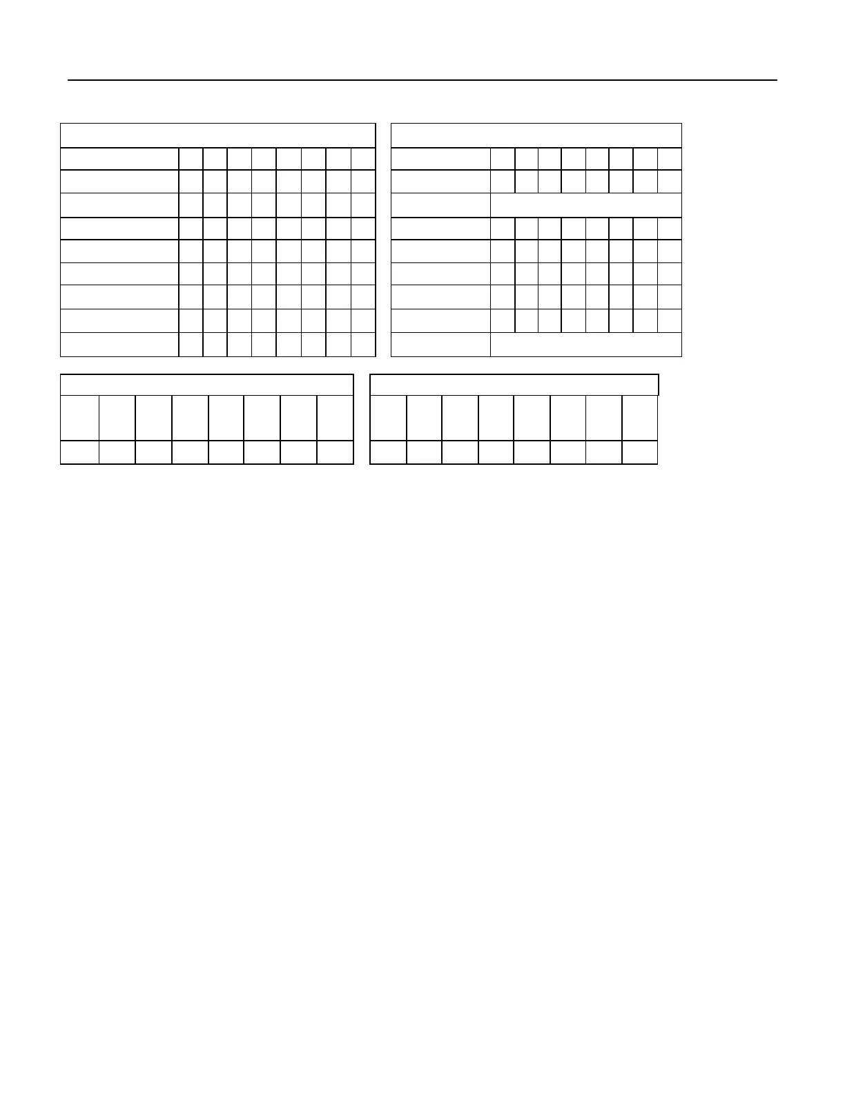
11.60 Write DMA (CAh/CBh)
Command Block Output Registers
Command Block Input Registers
Table 251 Write DMA Command (CAh/CBh)
The Write DMA command transfers one or more sectors of data from the host to the device, then the data is written
to the disk media.
The sectors of data are transferred through the Data Register 16 bits at a time.
The host initializes a slave-DMA channel prior to issuing the command. Data transfers are qualified by DMARQ and
are performed by the slave-DMA channel. The device issues only one interrupt per command to indicate that data
transfer has terminated and status is available.
If an uncorrectable error occurs, the write will be terminated at the failing sector.
Output Parameters To The Device
The number of continuous sectors to be transferred. If zero is specified, then 256
sectors will be transferred.
The sector number of the first sector to be transferred. (L=0)
In LBA mode, this register contains LBA bits 0 – 7. (L=1)
The cylinder number of the first sector to be transferred. (L=0)
In LBA mode, this register contains LBA bits 8 – 15 (Low), 16 – 23 (High). (L=1)
The head number of the first sector to be transferred. (L=0)
In LBA mode, this register contains LBA bits 24 – 27. (L=1)
The retry bit, but this bit is ignored.
Input Parameters From The Device
The number of requested sectors not transferred. This will be zero, unless an
unrecoverable error occurs.
The sector number of the last transferred sector. (L=0)
In LBA mode, this register contains current LBA bits 0 – 7. (L=1)
The cylinder number of the last transferred sector. (L=0)
In LBA mode, this register contains current LBA bits 8 – 15 (Low), 16 – 23 (High). (L=1)
The head number of the last transferred sector. (L=0) In LBA mode, this register
contains current LBA bits 24 – 27. (L=1)