16
Western Digital Hard Disk Drive OEM Specification
6.1.2.1 TX+ / TX- (SATA)
These signals are the outbound high-speed differential signals that are connected to the serial ATA cable
6.1.2.2 RX+ / RX- (SATA)
These signals are the inbound high-speed differential signals that are connected to the serial ATA cable.
6.1.2.3 5V Precharge
+5 Vdc that is available on the extended pins. It is used for Precharge when connected to backplane incorporated
feature.
6.1.2.4 12V Precharge
+12 Vdc that is available on the extended pins. It is used for Precharge when connected to backplane incorporated
feature.
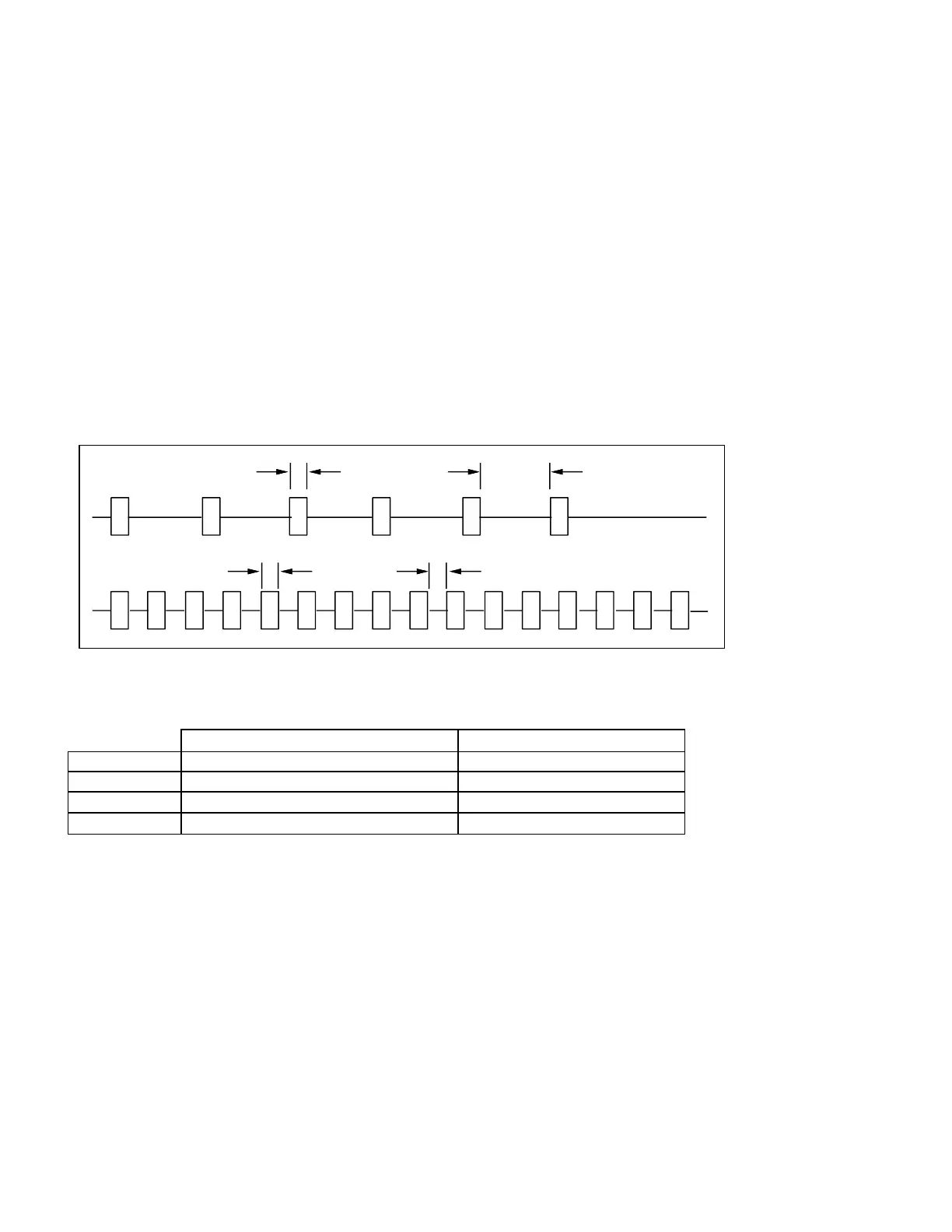
6.1.3 Out of Band Signaling (SATA)
Figure 4 The timing of COMRESET, COMINIT and COMWAKE
Table 12 Parameter Descriptions
6.1.4 Voltage and Ground Signals
The 12V and 5V contacts provide all of the voltages required by the drive. The two voltages share a common ground
plane to which all of the ground contacts are connected.
6.1.5 Ready LED Output
The drive provides an open-drain driver with 15mA of current sink capability to the Ready LED Output signal. The
cathode of the LED should be connected to this signal. The LED and the current-limiting resistor must be provided by
the enclosure.
COMRESET/COMINIT
t1
t2
t3
t4
COMWAKE