38
Western Digital Hard Disk Drive OEM Specification
8.4 Cylinder Low Register
This register contains the low order bits of the starting cylinder address for any disk access. At the end of the
command, this register is updated to reflect the current cylinder number.
In LBA Mode this register contains Bits 8-15. At the end of the command, this register is updated to reflect the
current LBA Bits 8-15.
The cylinder number may be from zero to the number of cylinders minus one.
When 48-bit addressing commands are used, the “most recently written” content contains LBA Bits 8-15, and the
“previous content” contains Bits 32-39.
8.5
Device Control Register
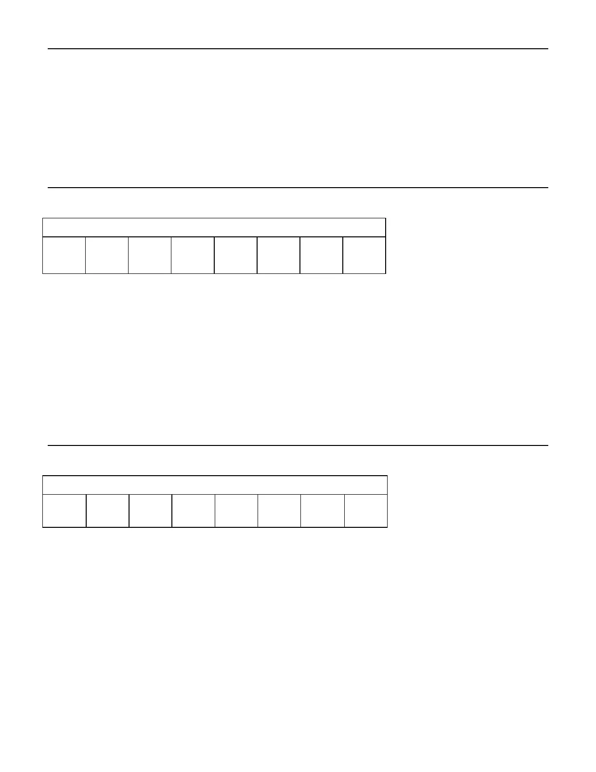
Table 28 Device Control Register
HOB (high order byte) is defined by the 48-bit Address feature set. A write to any Command
Register shall clear the HOB bit to zero.
Software Reset. The device is held reset when RST=1. Setting RST=0 re-enables the device.
The host must set RST=1 and wait for at least 5 microseconds before setting RST=0, to
ensure that the device recognizes the reset.
Interrupt Enable. When –IEN=0, and the device is selected, device interrupts to the host will be
enabled. When –IEN=1, or the device is not selected, device interrupts to the host will be
disabled.
8.6 Device/Head Register
Table 29 Device/Head Register
This register contains the device and head numbers.
Binary encoded address mode select. When L=0, addressing is by CHS mode. When L=1,
addressing is by LBA mode.
Device. This product ignores this bit.
Head Select. These four bits indicate binary encoded address of the head. HS0 is the least
significant bit. At command completion, these bits are updated to reflect the currently
selected head.
The head number may be from zero to the number of heads minus one.
In LBA mode, HS3 through HS0 contain bits 24-27 of the LBA. At command completion,
these bits are updated to reflect the current LBA bits 24-27.