Operation
0515−1/A1
Winterthur Gas & Diesel Ltd.
3/ 8
2.3 Procedure
3
1
3
010.513/02
Min.
Max.
2
4
WCH01185
Min.
Max.
1
4
3
2
WCH01185
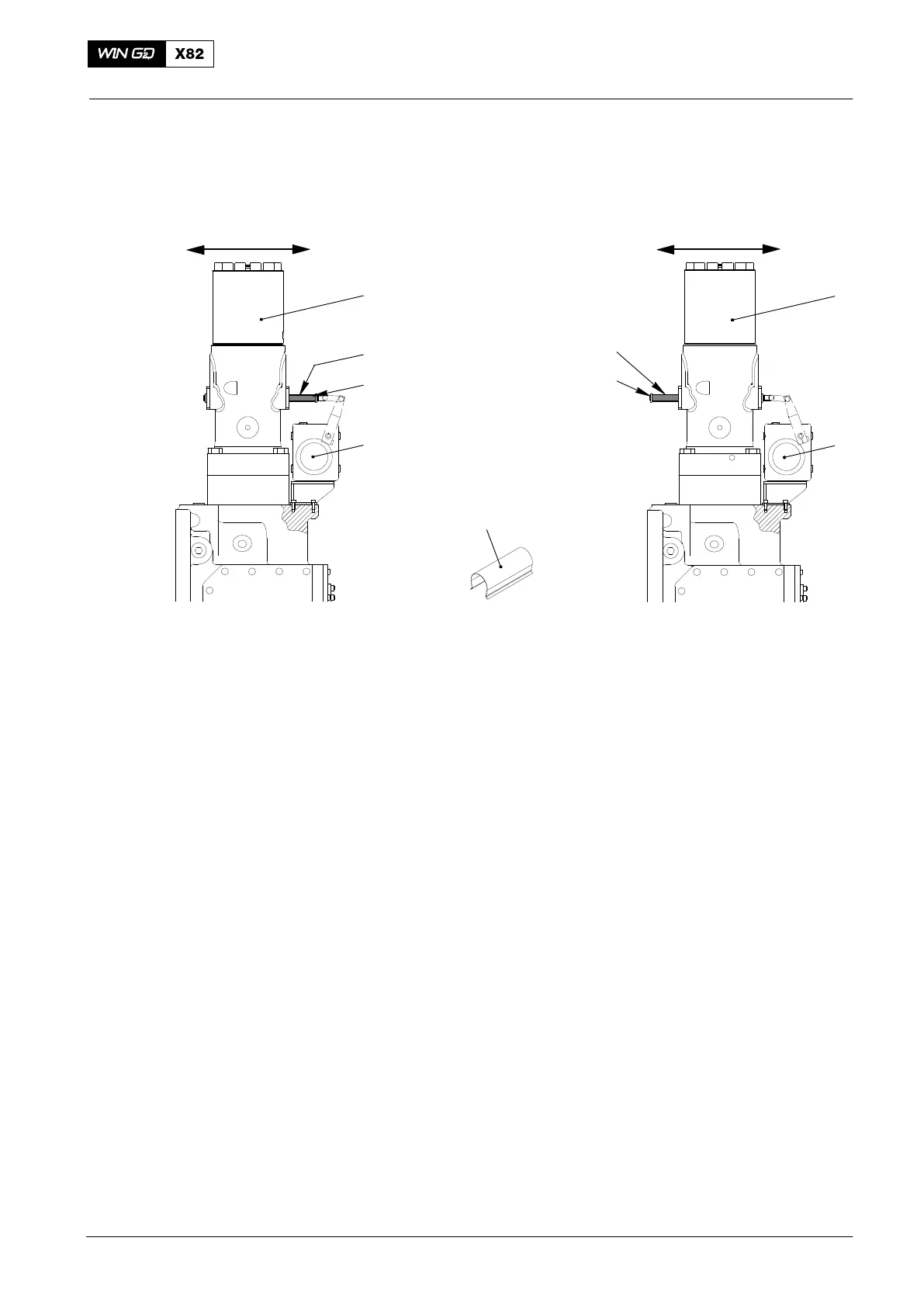
Minimum Position Maximum Position
Fig. 1: Minimum / Maximum Position of the Regulating Linkage
1 Fuel pump 3.14 3 Spacer (tool 94555)
2 Toothed rack 4 Actuator 3.21
2.3.1 One Actuator is Defective
1) Do a check of the control signals from the WECS−9520 and the electrical cables.
If necessary, replace the electrical cables.
2) Make sure that the regulating linkage moves freely.
3) Install the spacer (3, Fig. 1) (tool 94555) to the toothed rack (2) in the position
minimum on the fuel pump (1) that has the defective actuator (5).
4) Replace the defective actuator as soon as possible (see 5801−1 Regulating
Linkage in the Maintenance Manual).
Note: Related to the necessary power output, you can install the spacer (3,
Fig. 1) (tool 94555) as an alternative in the position maximum. Fuel
pressure regulation through the fuel pressure control valve 3.06 must be
prevented if possible.
5) Turn the knurled screw on the fuel pressure control valve 3.06 (see 5562−1) fully
counterclockwise.
2.3.2 All Actuators are Defective
1) Install the spacers (3, Fig. 1) (tool 94555) to the toothed racks (2). One half of the
fuel pumps in the position minimum and the other half in the position maximum.
Note: For higher loads set more fuel pumps to the position maximum.
2) Turn the knurled screw on the fuel pressure control valve 3.06 (see 5562−1) fully
counterclockwise.
2014
Faults in High Pressure Fuel System