Operation4002−1/A1
Winterthur Gas & Diesel Ltd.
10/ 15
4.3.4 Injection Control
Fuel injection is controlled as follows:
D Data from the crank angle and VIT are used to calculate the injection start.
The rail valves are activated to release the injection.
D The time difference between the injection start signal and the injection start is
known as the injection deadtime. The injection start is sensed when the fuel
quantity piston moves.
D The stroke of the fuel quantity piston gives the injection quantity. The injection is
stopped when the fuel quantity piston is at the calculated stroke.
D The governor calculates the injection quantity, which is related to the control
signal.
D On the subsequent injection cycle, the calculation of the correct injection time
includes the measured injection deadtime.
D The operation of the injection system is monitored at each cycle.
4.3.5 Reverse
For operation of the the engine in ASTERN, the crank angle is mirrored.
4.3.6 Emergency Mode
If the fuel quantity sensor is defective, the control system changes the fuel command
signal from the related FCM−20 into a time period. The related cylinder is then
controlled with timed injection.
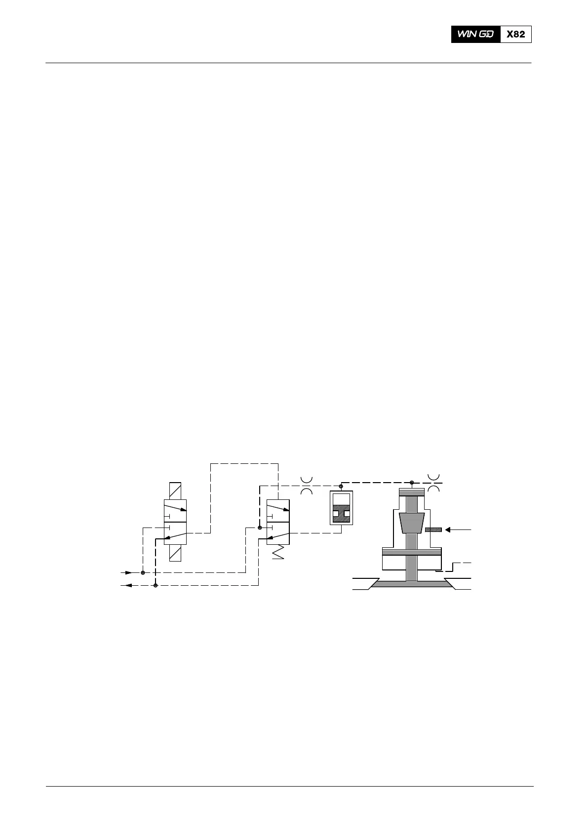
4.4 Exhaust Valve Control
All components shown in
the CLOSED position
Position
Sensor
Air Spring
Air
Rail Valve
OrificeOrifice
Exhaust Valve
Control Unit
Exhaust
Control Valve
Servo
Oil
Fig. 8: Exhaust Valve Control
4.4.1 Exhaust Valve − Function
The exhaust valve opens and closes once each full turn of the crankshaft. The valve
stroke sensor measures the exhaust valve movement.
The FCM−20 amplifies the control outputs up to the necessary signals for the rail
valves.
4.4.2 Rail Valve ON-time Measurement
The time between the start signal and the valve piston movement is measured, then
shown in the remote control.
Engine Control System WECS-9520
2014