Tempro basic C 90 & Tempro primus C 90
Page 16
BASIC & PRIMUS C90 V 3.0 english / 10.04.2012
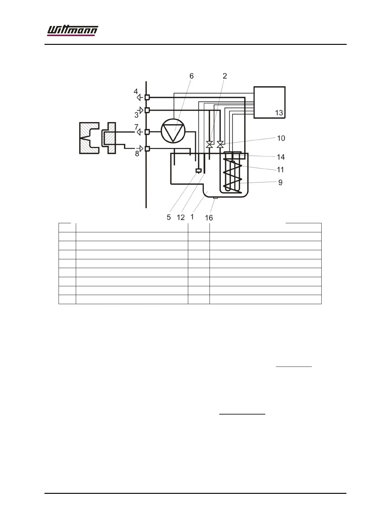
Diagram of temperature stabilizing circuit: Tempro primus C 90
1 Heat exchanger 9 Heater element
2 Filling solenoid valve 10 Cooling solenoid valve
3 Cooling-water inlet 11 Cooling coil
4 Cooling-water outlet 12 Temperature sensor
5 Level switch 13 Microprocessor controller
6 Pump 14 Safety temperature cutout
7 Mould connection-FEED 15
8 Mould connection-RETURN 16 Drain plug
The temperature stabilizing circuit includes a heat exchanger (1). The heat exchanger is
filled with water automatically through a solenoid valve (2). (Capacity approx. 9 litres
Tempro basic / primus C90).
Joint water feed for filling (2) and cooling (10) solenoid valves through coarse filter. The
filling height is controlled by the level switch (5).
The temperature stabilizing medium is driven by the pump (6) in an open circuit through
the mould circuit and runs back into the heat exchanger. Mould connections feed and
return (7,8).
The water is heated by the heating element (9) inside the heat exchanger. When the
cooling solenoid valve (10) is opened the cooling water flows through the cooling spiral
(11) and cools the temperature stabilizing medium (indirect cooling).
Cooling water feed and return (3,4).
The medium temperature is monitored by the temperature sensor (12) and closely
controlled by an advanced microprocessor controller (13).
The measuring accuracy is 0.1 degrees and therefore allows for a constant temperature of
+/- 0,5 degrees in the injection mould.
Please read thoroughly the following chapters which contain important
information about installation, start-up, operation, and maintenance.