Tempro basic C 90 & Tempro primus C 90
Page 54
BASIC & PRIMUS C90 V 3.0 english / 10.04.2012
11.5 Connection cables
These connection cables are required for the series connection from Tempro basic C
90 to another Tempro basic C 90.
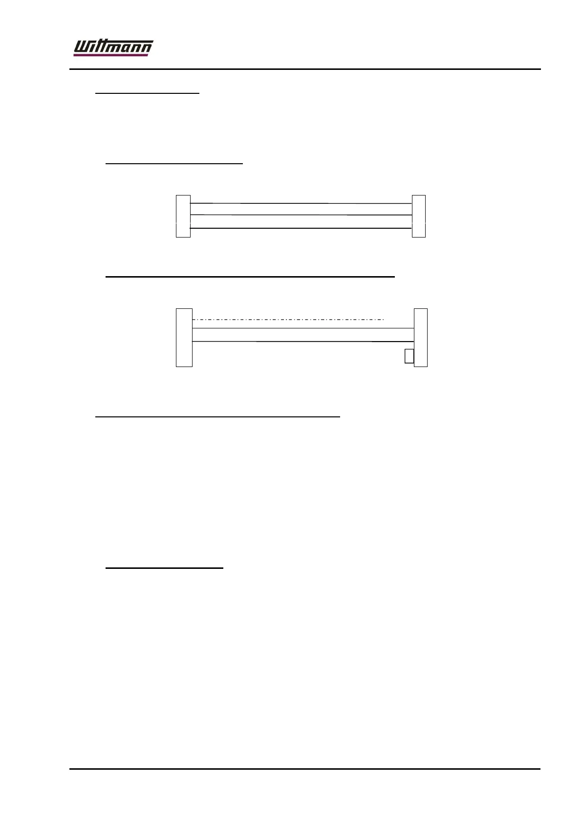
11.5.1 Series interfacing RS232
T5 0000 1630
TxD (Green) 2 2
RxD (White) 3 3
GND (Brown) 7 5
TG1: SubD 25-pin TG2: SubD 9-pin
11.5.2 Series interfacing 20mA (identical with Engel 20mA)
T5 0000 1620
Screen 1
TxD + (White) 24
3
RxD - (Brown) 10
7
4
6
IMM: SubD 25-pin TG: SubD 9-pin
11.6 Pressure Measurement with Flow Indication
The device series Basic C90 can be equipped with the option “Pressure
measurement“ and “Flow indication”.
The flow rate is calculated from the parameters of the pump characteristics and
the pump delivery pressure and displayed.
Accuracy:
P1 0,1 bar
l/min 2,0 to 8,5 l/min
(Max. flow rate at 0 bar / max. pressure at 0 l/min)
11.6.1 Flow rate measuring:
In this model, the flow rate is determined by measuring the system pressure and
the total pressure. To do this, the user must determine various data during the
calibration process and enter the respective values in the configuration menu
(„con“, code120).
This flow rate is then calculated based on these values and the pump pressure
(difference between total and system pressure).
Procedure:
In the140° model, the pump is stopped for 5 seconds when the nominal
temperature is reached. At the end of the 5-second period, the pressure is
measured and saved as the system pressure. The pump is subsequently
restarted.