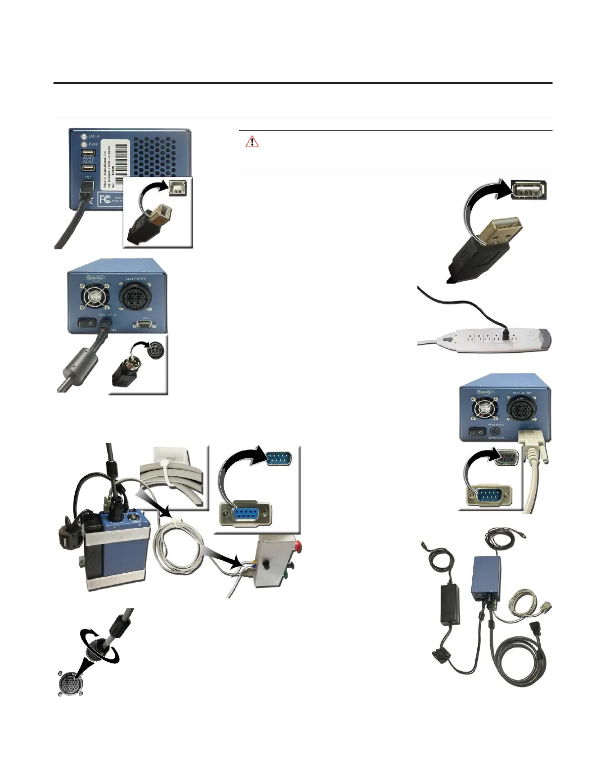
Connect the ECU
* WARNING: High voltage. No user
serviceable parts inside the ECU.*
1. Connect ECU USB cable to the matching port on the
front of the ECU.
2. Plug the other end of the USB cable into the USB
port on the computer. If your system came with
a USB hub, plug it in between the ECU and the
computer.
3. Connect the power output cable to the back of the
ECU.
4. Connect the ECU power supply to the surge
protector.
5. Connect the DB9 cable to the ECU.
6. Connect the other end of the
DB9 cable to the control panel
box on the back of the board.
7. Locate the zip tie and slip it
through the plastic mount
attached to the back of the
board.
8. Take the excess DB9
cable and loop it
around a couple of
times then use the
zip tie to attach it to
the plastic mount on
the back of the
board.
9. The board cable was plugged into the back of the
ECU when we hooked up the gantry previously. See
“Connecting the Board Cable” page 11 for more
information.
10. The ECU is now connected. 10. The ECU is now connected.
14
20-36070-1 GettingStartedManualZ1FrameShop
04/07/21
Wizard™ CMC Model Z1 Hardware and Software Getting Started Guide