2-23
Installation Information CT Hoods and DD Ventilation
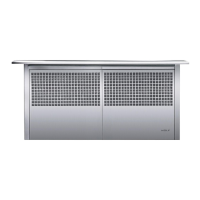
DOWNDRAFT INSTALLATION REQUIREMENTS
ELECTRICAL REQUIREMENTS
Wolf downdraft ventilation systems require a separate, grounded 120 VAC, 60 Hz power supply (for ICB power
requirements see Section 6). The service should have its own 15 amp circuit breaker, and a grounded 3-prong re-
ceptacle should be located within the reach of the 2-1/2’ (.8 m) power cord. The specifi c location of the outlet is not
critical, as long as it is within reach of the power cord that is located mid-way, top and bottom, on the right side of the
downdraft.
NOTE: If Model DD30 is to be installed in a 30” (762) wide cabinet, Model DD36 in a 36” (914) wide cabinet or Model
DD45 in a 45-1/2”(1156) wide cabinet, the electrical outlet cannot be located on the back wall of the cabinet. The
outlet can be placed in an adjacent cabinet within reach of the power cord. An access hole for the power cord must
be drilled in the cabinet wall.
CONTROL MODULE LOCATION
Installation of the remote-mounted control module can be located anywhere within 10’ (3 m) of the downdraft assem-
bly and a minimum of 4” (102) from the outer edge of cooktop element or burner. You will be required to drill three
holes and connect the control module to the downdraft assembly using the cable provided.
NOTE: The length of the control module cable is 10’ (3 m). You must plan the installation of the control module to be
within 10’ (3 m) of the downdraft assembly.
The remote-mounted control module is 2-3/8” (60) x 6-5/8” (168) and can be positioned horizontally or vertically in the
countertop. A 5/8” (16) diameter hole for the DIN connector cable will be centered horizontally and vertically in the
back side of the control module. Two 1/4” (6) diameter holes for the mounting screws will be located 2” (51) from the
center of the DIN connector cable hole, one on each side. Additional installation instructions are provided with the
control kit. Mark the center of the control module on the counter top. Measure 2” (51) up (or left) and 2” (51) down (or
right) to locate holes for the mounting screws.
DOWNDRAFTS MUST BE PROPERLY GROUNDED. UNIT SHOULD BE CONNECTED ELECTRICALLY BY A
QUALIFIED ELECTRICIAN IN ACCORDANCE WITH ALL APPLICABLE NATIONAL AND LOCAL ELECTRICAL
CODES.
DO NOT USE AN EXTENSION CORD OR TWO-PRONG ADAPTER. ELECTRICAL GROUND IS REQUIRED ON
THIS APPLIANCE. DO NOT REMOVE THE POWER SUPPLY CORD GROUND PRONG.
NOTE: A ground fault circuit interrupter (GFCI) is not recommended and may cause interruption of operation.
THE DOWNDRAFT MUST BE USED WITH A WOLF APPROVED CONTROL MODULE AND TOP COVER.