Access & Removal CT Hoods and DD Ventilation
4-5
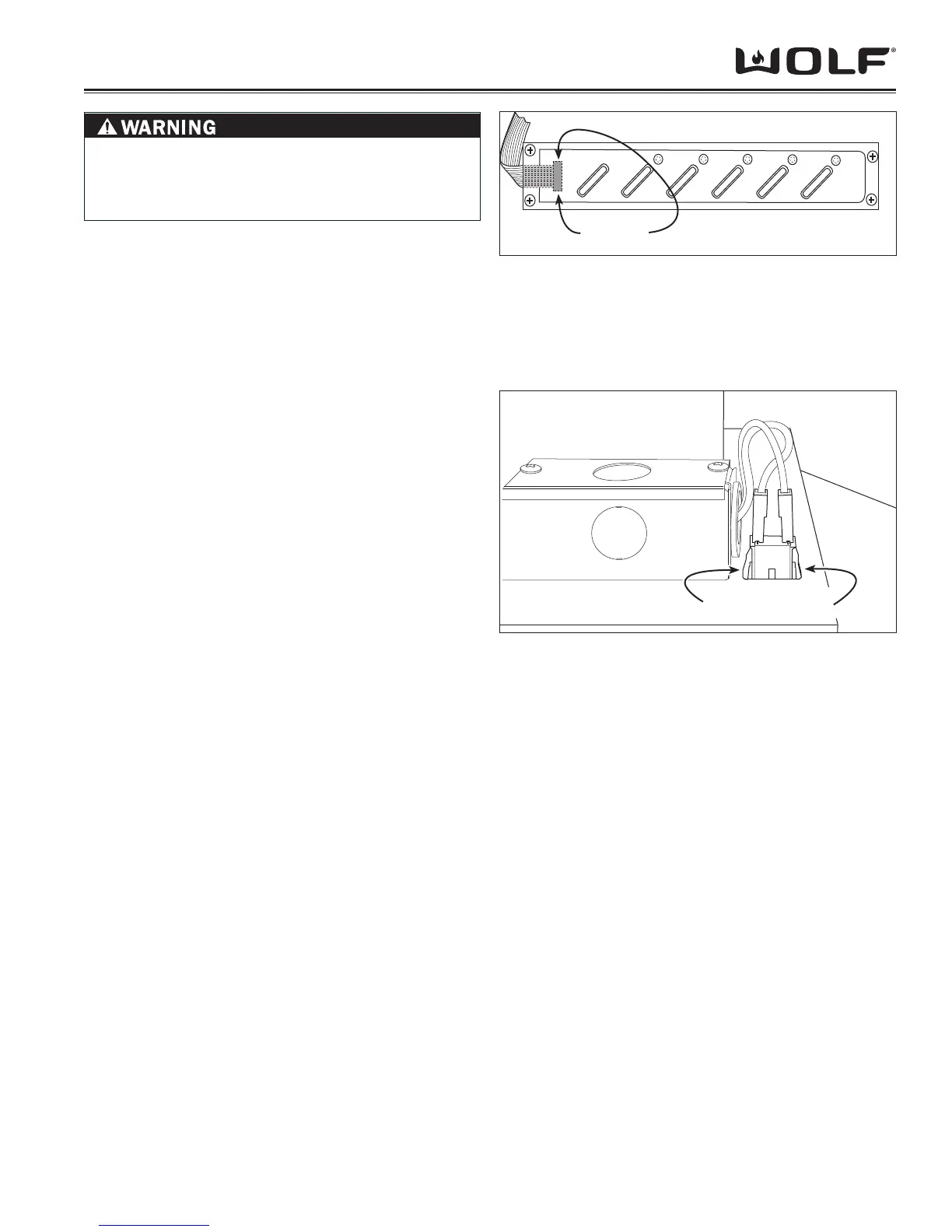
Figure 4-7 User Interface Switch Bracket Removal
Figure 4-8 Power Outlet Removal
RIBBON CABLE REMOVAL
NOTE: Refer to all WARNINGS and CAUTIONS at be-
ginning of this section.
The user interface switch consists of a plastic housing
which contains the circuit board and push buttons, and a
clear plastic plate that secures the push buttons in place
and captivates the control ribbon. Screws secure the
clear plastic plate to the housing.
To remove the control ribbon and/or to replace the circuit
board, the fi lters, lamp holder support and the user inter-
face switch mounting bracket must be removed fi rst, then
(See Figure 7):
Extract the screws securing the clear plastic plate to 1.
the housing.
Lift control circuit board out of housing.2.
With thumb and forefi nger, grasp the ribbon cable 3.
connector and disconnect from circuit board.
POWER OUTLET REMOVAL
NOTE: Refer to all WARNINGS and CAUTIONS at be-
ginning of this section.
To access the power outlet the lower section of the
telescoping chimney fl ue must be raised off of the hood
and temporarily secured in place. The outlets are located
on the top left front of the hood frame and are secured in
place with spring clips.
To remove the power outlets, (See Figure 8):
Raise lower section of chimney fl ue off of hood frame 1.
and temporarily secure in position.
Disconnect electrical leads from outlet.2.
With fi ngers, depress spring clips on sides of outlet 3.
and push through hood frame.
Depress these tabs
Grab here
TO AVOID ELECTRIC SHOCK, POWER TO THE
VENTILATION UNIT MUST BE DISCONNECTED
WHENEVER PERFORMING THE FOLLOWING
REPAIRS.