Access & Removal CT Hoods and DD Ventilation
4-15
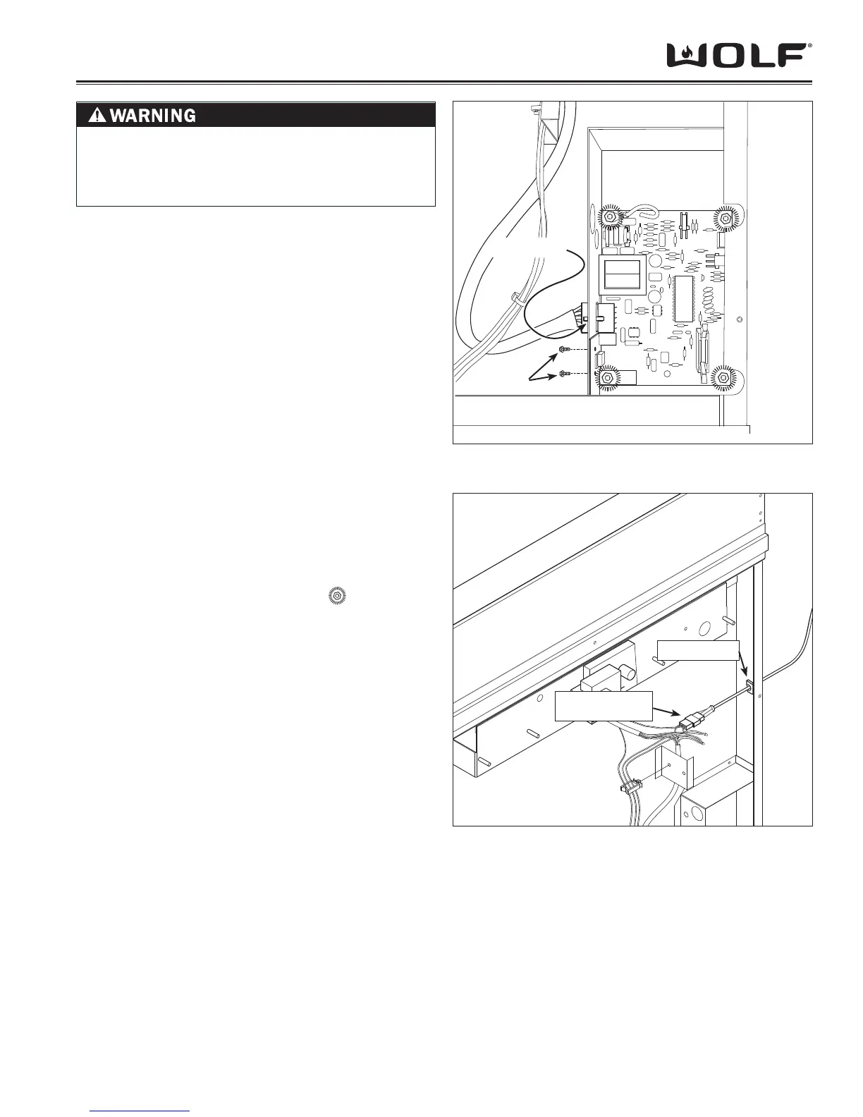
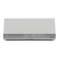
Figure 4-33 Power Control Board Removal
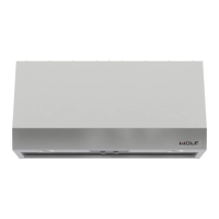
Figure 4-34 Power Cord Removal
POWER CONTROL BOARD REMOVAL
NOTE: Refer to all WARNINGS and CAUTIONS at
beginning of this section.
The power control board is located inside a compartment
of the bottom right hand corner of the unit interior. The
board sits upon nylon spacers and is secured by nuts to
the threaded studs pressed into the unit frame. Screws
pass through the left compartment sidewall and fasten
into an aluminum bracket riveted to the power control
panel.
To remove the power control board, the internal blower
assembly and the lower airbox panel must be removed
fi rst, then (See Figure 33):
From the left side of the power control board com-1.
partment, depress retaining clip and disconnect wire
harness from power control board.
From same side of compartment sidewall, extract 2.
screws that fasten into the aluminum bracket of the
power control board.
From inside compartment, using an 11/32” (8.75) 3.
socket with extension, remove nuts from corners
of power control board.
Lift power control board off of threaded studs.4.
POWER CORD REMOVAL
NOTE: Electrical shock hazard. Refer to WARNING at
beginning of section.
The power cord enters the unit from the right side and is
held in place by a strain relief located in the right sidewall
of the unit.
To remove the power cord, the internal blower assem-
bly and lower airbox panel must be removed, then (See
Figure 34):
Disconnect power cord from wire harness at quick 1.
disconnect.
From inside of unit with fl at bladed screwdriver, 2.
compress and push strain relief through opening in
sidewall. Pull power cord out of unit.
Quick Connect
Strain Relief
Press Here
Screws
TO AVOID ELECTRIC SHOCK, POWER TO THE
VENTILATION UNIT MUST BE DISCONNECTED
WHENEVER PERFORMING THE FOLLOWING
REPAIRS.