2-7
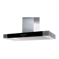
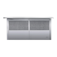
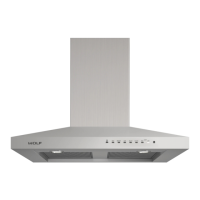
Installation Information CT Hoods and DD Ventilation
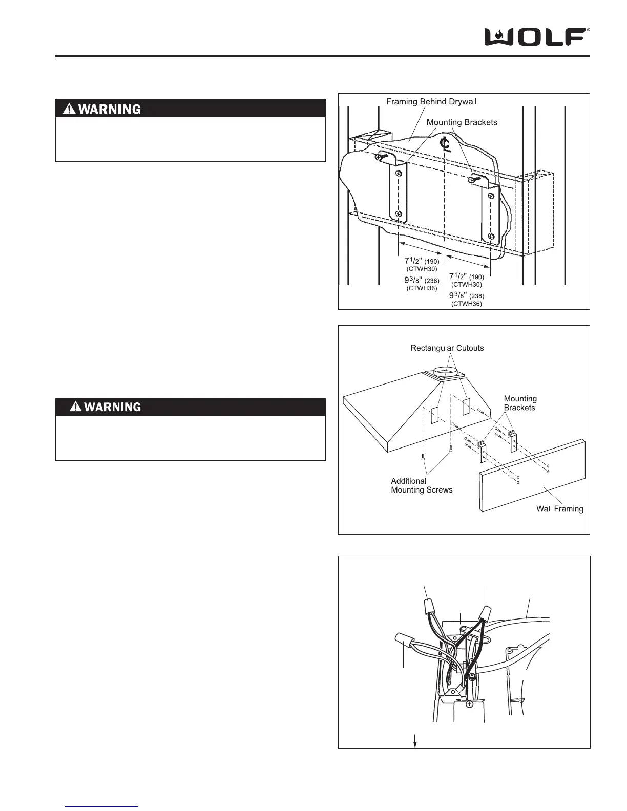
Figure 2-10 Mounting Bracket Installation
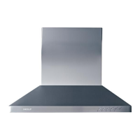
Figure 2-11 Hood Installation
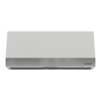
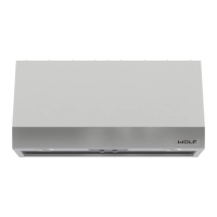
CT WALL HOOD INSTALLATION
INSTALL MOUNTING BRACKETS
Construct wood wall framing that is fl ush with the interior
surface of the wall studs. Make sure that the framing is
centered in the hood installation location, and that the
height of the framing will allow the mounting brackets to
be secured to the framing within the dimension shown in
Figure 2-10.
After the wall surface is fi nished, secure the mounting
brackets to the framing using the dimensions shown.
INSTALL THE HOOD
Hang the hood from the brackets through the rectangular
cut-outs on the back of the hood. The cut-outs are larger
than the brackets to allow for vertical and horizontal
adjustment. (See Figure 2-11)
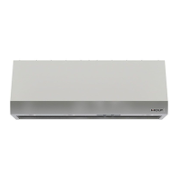
Keep in mind that the bottom of the hood should be 24”
(610) to 30” (762) above the countertop.
Use height adjustment screws to adjust the hood vertically
and the depth adjustment screws to adjust the hood
horizontally.
Secure the hood with additional mounting screws. If wall
studs or framing are not available in the proper location,
use the drywall anchors provided with the hood.
ELECTRICAL CONNECTIONS
NOTE: This unit should be install by a qualifi ed electrician
in accordance with all applicable national and local codes.
Remove the cover from the rear electrical box knockout 1.
that faces the hood’s discharge collar.
Insert 6” (152) of 120 VAC power cable through the 2.
knockout opening. Secure the cable to the electrical
box with an appropriate connector.
Make electrical connections. Connect black to black, 3.
white to white and green/yellow to green or bare wire.
(See Figure 2-12)
Reinstall the electrical box cover and screws. Make 4.
sure that all wires are secure and that no wires are
pinched between the cover and box.
Green/Yellow to
Green or
Bare Wire
Black to
Black
HOOD FRONT TOP OF HOOD SHELL
Discharge
Collar
120 V AC
Power Cable
Rear
Electrical
Box
White
to White
Figure 2-12 Electrical Connections
TO REDUCE THE RISK OF ELECTRICAL SHOCK,
THIS VENTILATION HOOD MUST BE PROPERLY
GROUNDED.
DUE TO THE WEIGHT OF SOME HOODS, SEVERAL
PEOPLE MAN BE REQUIRED FOR A SAFE AND
PROPER INSTALLATION.