ENGINE
STW34, STW37, STW40, WSM
1-S68
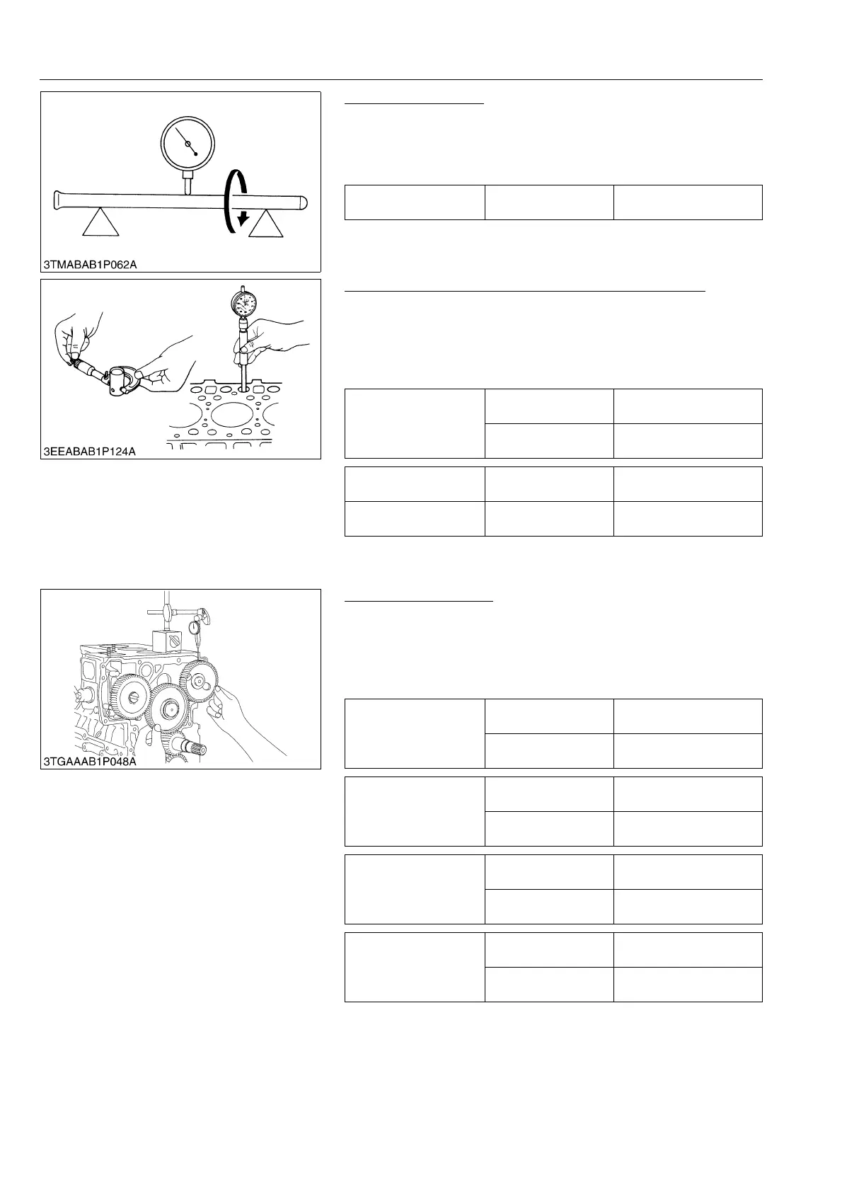
Push Rod Alignment
1. Place the push rod on V blocks.
2. Measure the push rod alignment.
3. If the measurement exceeds the allowable limit, replace the
push rod.
9Y1211109ENS0103US0
Oil Clearance between Tappet and Tappet Guide Bore
1. Measure the tappet O.D. with an outside micrometer.
2. Measure the I.D. of the tappet guide bore with a cylinder gauge,
and calculate the oil clearance.
3. If the oil clearance exceeds the allowable limit or the tappet is
damaged, replace the tappet.
9Y1211109ENS0104US0
(2) Timing Gears, Camshaft and Fuel Camshaft
Timing Gear Backlash
1. Set a dial indicator (lever type) with its tip on the gear tooth.
2. Move the gear to measure the backlash, holding its mating gear.
3. If the backlash exceeds the allowable limit, check the oil
clearance of the shafts and the gear.
4. If the oil clearance is not proper, replace the gear.
9Y1211109ENS0105US0
Push rod alignment Allowable limit
0.25 mm
0.0098 in.
Oil clearance between
tappet and tappet guide
bore
Factory specification
0.020 to 0.062 mm
0.00079 to 0.00244 in.
Allowable limit
0.07 mm
0.003 in.
Tappet O.D. Factory specification
23.959 to 23.980 mm
0.94327 to 0.94409 in.
Tappet guide bore I.D. Factory specification
24.000 to 24.021 mm
0.94489 to 0.94570 in.
Backlash between idle
gear and crank gear
Factory specification
0.0415 to 0.1122 mm
0.94327 to 0.94409 in.
Allowable limit
0.15 mm
0.0059 in.
Backlash between idle
gear and cam gear
Factory specification
0.0415 to 0.1154 mm
0.001634 to 0.004543 in.
Allowable limit
0.15 mm
0.0059 in.
Backlash between idle
gear and injection pump
gear
Factory specification
0.0415 to 0.1154 mm
0.001634 to 0.004543 in.
Allowable limit
0.15 mm
0.0059 in.
Backlash between crank
gear oil pump gear
Factory specification
0.0415 to 0.1090 mm
0.001634 to 0.004291 in.
Allowable limit
0.15 mm
0.0059 in.
 Loading...