CLUTCH
STW34, STW37, STW40, WSM
2-S30
[3] DISASSEMBLING AND ASSEMBLING
Clutch Assembly
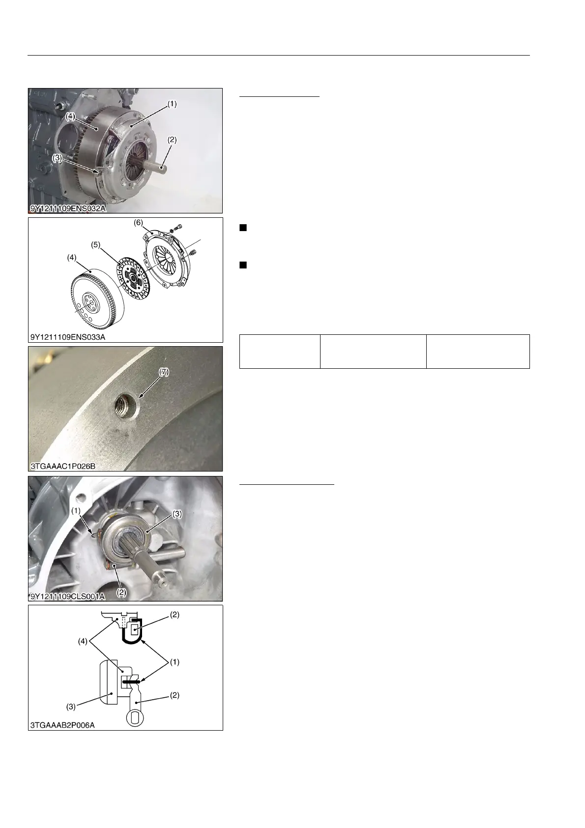
1. Remove the clutch mounting screws and remove the clutch
assembly (1) from the flywheel (4).
(When reassembling)
• Direct the shorter end of the clutch disc boss toward the
flywheel (4).
• Apply molybdenum disulphide (Three Bond 1901 or equivalent)
to the splines of clutch disc boss.
• Screws in two reamer screws (3) in the reamer screw holes (7).
• After tightening the reamer screws (3), tighten the other general
screws.
• Align the center of clutch disc (5) and flywheel (4) by
inserting the clutch center tool (2).
• Do not allow grease and oil on the clutch disc facing.
• The reamer screw hole (7) on the clutch cover is in the next
of the 5 mm (0.2 in.) dia. hole.
• The shape of the reamer screw hole (7) on the flywheel (4)
is different from other screw holes.
9Y1211109ENS0034US0
Clutch Release Fork
1. Remove the set spring (1) from clutch release fork (2) and
release hub.
2. Remove the release bearing (3) with release hub (4).
(When reassembling)
• Set the clutch release fork (2) and release hub (4) with set
spring (1) in the correct direction.
9Y1211109CLS0006US0
Tightening torque Clutch mounting screw
23.5 to 27.5 N·m
2.4 to 2.8 kgf·m
17.4 to 20.2 lbf·ft
(1) Clutch Assembly
(2) Clutch Center Tool
(3) Reamer Screw
(4) Flywheel
(5) Clutch Disc
(6) Clutch Cover
(7) Screw Hole for Reamer Screw
(1) Set Spring
(2) Clutch Release Fork
(3) Release Bearing
(4) Release Hub



 To Next Page