TRANSMISSION
STW34, STW37, STW40, WSM
3-S45
(3) Separating Clutch Housing Case
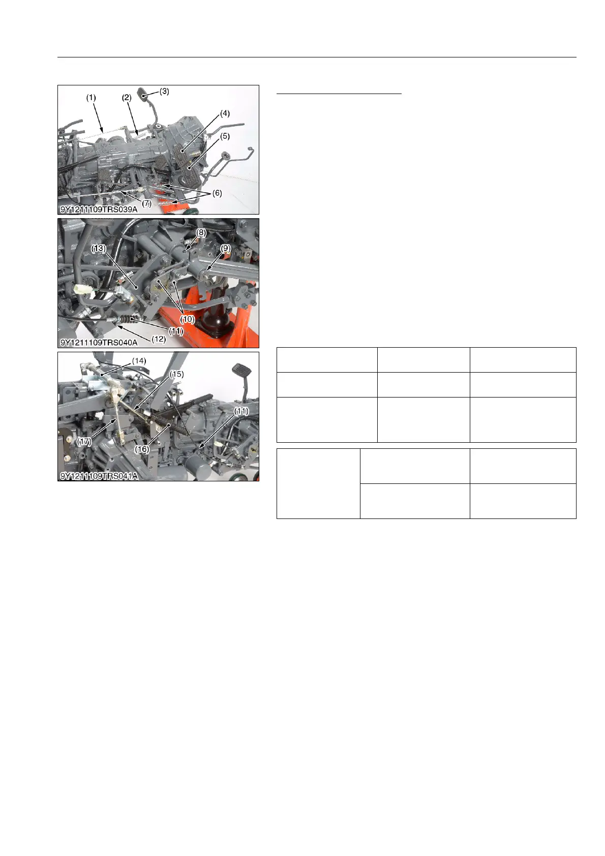
Clutch and Brake Linkage
1. Remove the brake rods (1), (7) and brake springs (6).
2. Remove the release wire (11).
3. Remove the brake link (10).
4. Remove the spring pin (8) and external snap ring (9), and
remove the brake pedals (4), (5).
5. Remove the pedal support assembly (13) with the brake switch.
6. Remove the clutch rod and spring (2), and draw out the clutch
pedal (3) with the brake shaft.
7. Remove the damper (16).
8. Remove the parking brake stay assembly (14) with the parking
brake rod 1 (15) and parking brake rod 2 (17).
(When reassembling)
• Reassemble the release wire (11) to the guide plate (12) so that
the guide plate (12) comes to the center of the threaded portion.
• Apply grease to the brake link (10).
• After reassembling the brake link (10), do the check of "3) Brake
Link (Cruise Control)" (See page 3-S14).
• Adjust the clutch pedal free travel (See page 2-S4).
• Adjust the brake pedal free travel (See page 5-S4).
• Adjust the parking brake lever free travel (See page 5-S4).
9Y1211109TRS0029US0
Clutch pedal free travel Factory specification
20 to 30 mm
0.78 to 1.18 in.
Brake pedal free travel Factory specification
20 to 30 mm
0.78 to 1.18 in.
Parking brake lever free
travel
Factory specification
The brake works when the
lever is raised until the
rachet sound is heard
twice.
Tightening torque
Brake link retaining nut
7.8 to 9.3 N·m
0.8 to 0.95 kgf·m
5.8 to 6.9 lbf·ft
Parking brake stay
assembly
48 to 55 N·m
4.9 to 5.7 kgf·m
36 to 41 lbf·ft
(1) Brake Rod (Left)
(2) Clutch Spring
(3) Clutch Pedal
(4) Brake Pedal (Left)
(5) Brake Pedal (Right)
(6) Brake Spring
(7) Brake Rod (Right)
(8) Spring Pin
(9) External Snap Ring
(10) Brake Link
(11) Release Wire (Cruise Control)
(12) Guide Plate
(13) Pedal Support Assembly
(14) Parking Brake Stay Assembly
(15) Parking Brake Rod 1
(16) Damper
(17) Parking Brake Rod 2



 To Next Page