ENGINE
STW34, STW37, STW40, WSM
1-S18
(4) Fuel System
Injection Timing
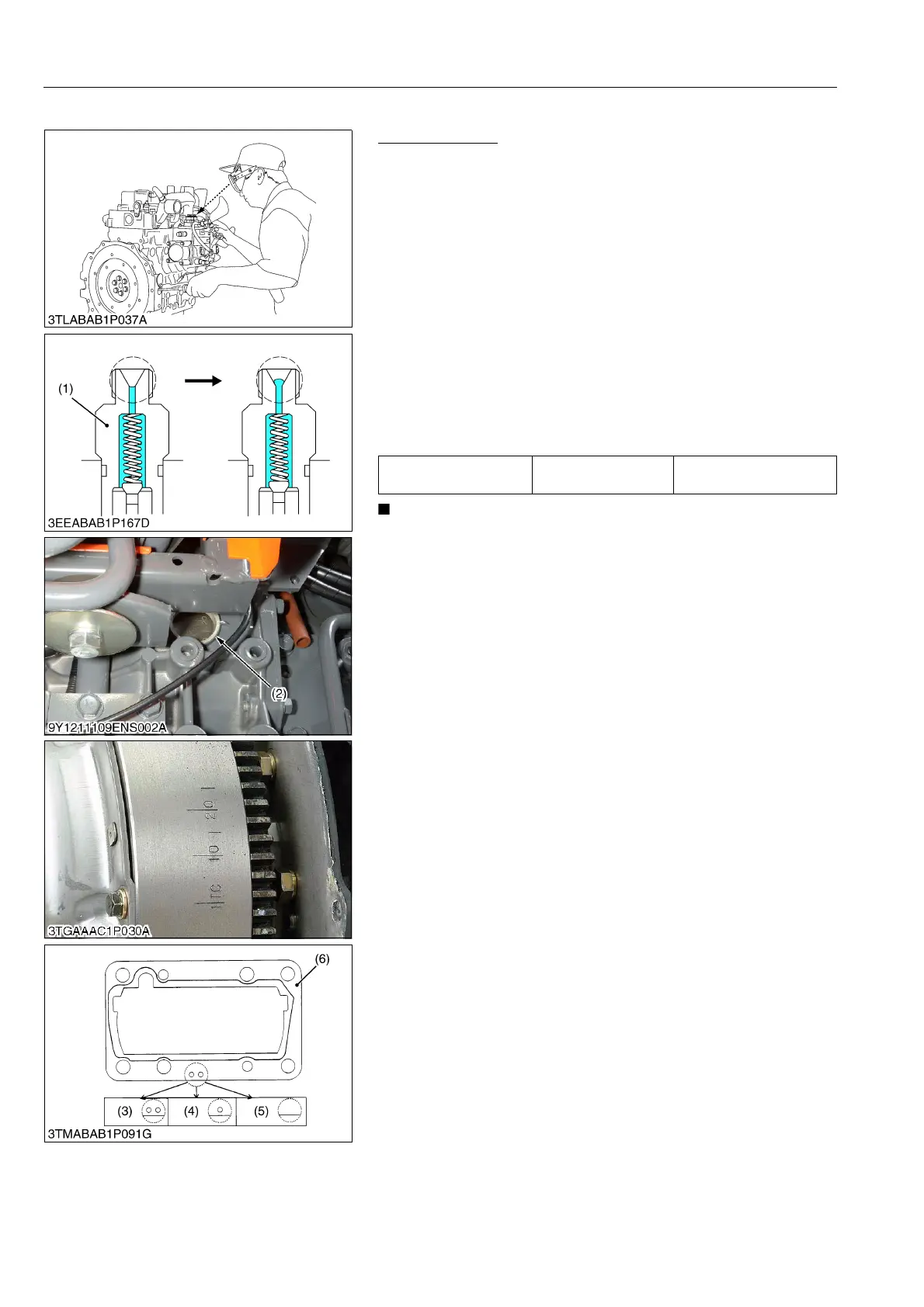
1. Remove the stop solenoid.
2. Remove the injection pipes and nozzle.
3. Remove the cap of the timing window (2) on the housing under
the right step.
4. Set the speed control lever to maximum fuel discharge position.
5. Turn the flywheel counterclockwise (facing the flywheel) until
the fuel fills up to the hole of the delivery valve holder (1) for 1st
cylinder.
6. Turn the flywheel further and stop turning when the fuel begins
to flow over, to get the present injection timing.
7. (The flywheel has mark 1TC and four lines indicating every
0.087 rad (5 °) of crank angle from 0.175 rad (10 °) to 0.436 rad
(25 °) before mark 1TC) Calculate the angle which the center of
the window points out.
8. If the calculation differs from specified injection timing, change,
add or remove the shim (6) to adjust.
• The sealant is applied to both sides of the soft metal gasket
shim. The liquid gasket is not required for assembling.
• Shims are available in thickness of 0.20 mm (0.0079 in.),
0.25 mm (0.0098 in.) and 0.30 mm (0.0118 in.). Combine
these shims for adjustments.
• Injection timing delays or advances by approx. 0.0087 rad
(0.5 °), when the thickness of the shim is increased or
decreased by 0.05 mm (0.002 in.).
• In disassembling and replacing, be sure to use the same
number of new shims with the same thickness.
9Y1211109ENS0013US0
Injection timing Factory specification
0.297 to 0.331 rad
(17 to 19 °) before T.D.C.
(1) Delivery Valve Holder
(2) Timing Window
(3) Two-holes: 0.20 mm (0.0079 in.)
(4) One-hole: 0.25 mm (0.0098 in.)
(5) Without hole: 0.30 mm (0.0118 in.)
(6) Soft Metal Gasket Shim