ELECTRICAL SYSTEM
STW34, STW37, STW40, WSM
9-S38
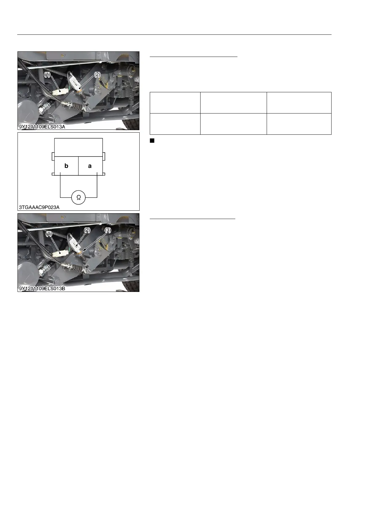
(25) Brake Light Switch
Brake Light Switch Continuity
1. Disconnect the 2P connector (1), and measure the resistance
with an ohmmeter across the brake switch leads.
2. If the measurement still differs from the table, replace the brake
light switch.
• Brake pedal free travel: 20 to 30 mm (0.79 to 1.18 in.)
9Y1211109ELS0068US0
Adjusting Brake Light Switch
1. Disconnect the connector (1) and remove the brake light switch
(2) once.
2. Depress the brake within the range of free travel (20 to 30 mm
(0.79 to 1.18 in.)) and hold it.
3. Connect the leads of the ohmmeter to the brake light switch lead
terminal.
4. Screw in the brake light switch (2) until the ohmmeter begins to
show "Infinity".
5. Further screw in the brake light switch by 1/2 turn and tighten
the lock nut (3).
9Y1211109ELS0069US0
Resistance (When
the switch push is
released)
a – b 0 Ω
Resistance (When
the switch push is
pushed)
a – b Infinity
(1) 2P Connector (2) Brake Light Switch
(1) Connector
(2) Brake Light Switch
(3) Lock Nut



 To Next Page