ELECTRICAL SYSTEM
STW34, STW37, STW40, WSM
9-S24
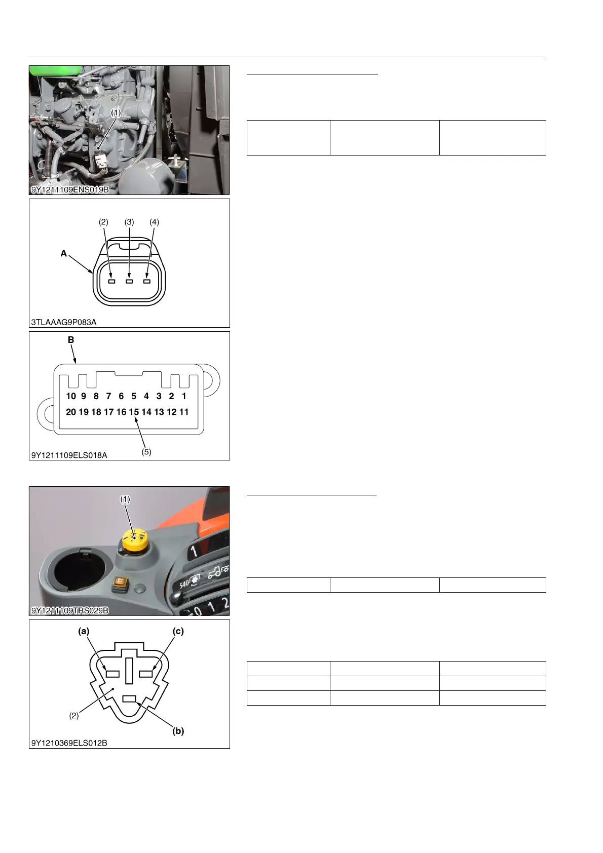
Engine Tachometer Sensor
1. Measure the resistance between terminal of panel and terminal
of sensor connector.
2. If 0 ohm is not indicated, the wiring harness is faulty.
9Y1211109ELS0078US0
(10) PTO Clutch Control Switch
PTO Clutch Control Switch
1) Connector Voltage
1. Remove the PTO switch connector (2).
2. Turn the main switch "ON" position.
3. Measure the voltage across terminal 2 (Harness) and chassis.
4. If the voltage differs from battery voltage, the wiring harness,
fuse, or main switch is faulty.
2) PTO Switch Continuity
1. Remove the PTO switch connector (1).
2. Check the continuity with an ohmmeter across the terminal 1 (a)
and terminal 2 (b), terminal 2 (b) and terminal 3 (c).
3. If connection does not change, PTO switch is faulty.
9Y1211109ELS0028US0
Resistance
Terminal 15 of panel
connector – Terminal 2 of
sensor connector
0 Ω
(1) Engine Tachometer Sensor
(2) Terminal 1
(3) Terminal 2
(4) Terminal 3
(5) Terminal 15
A: Connector of Wire Harness Side
B: Panel Connector of Wire Harness
Voltage Terminal 2 – Chassis Approx. battery voltage
Position Terminal 1 – terminal 2 Te rmi nal 2 – terminal 3
OFF 0 Ω Infinity
ON Infinity 0 Ω
(1) PTO Switch
(2) PTO Switch Connector
(a) Terminal 1
(b) Terminal 2
(c) Terminal 3
 Loading...