TRANSMISSION
STW34, STW37, STW40, WSM
3-S49
(6) Separating Transmission Case
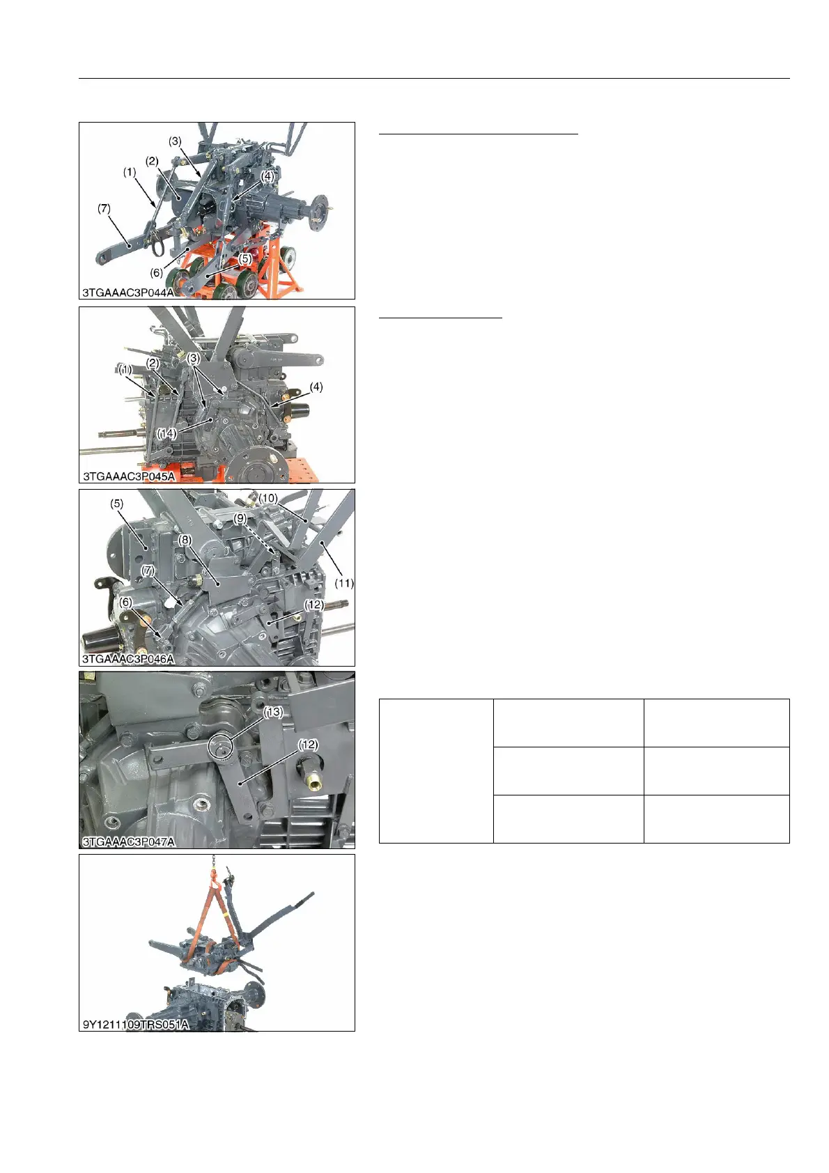
3 Points Linkage and Drawbar
1. Remove the lifting rods (1), (4).
2. Remove the top link (3) and PTO shaft cover (2).
3. Remove the lower links (5), (7) with the check chains.
4. Pill out the drawbar (6).
9Y1211109TRS0037US0
Hydraulic Cylinder
1. Remove the front drive rod (1), range gear shift rod (2) and mid
PTO rod (4).
2. Remove external snap ring and remove the brake lever (14),
(12).
3. Remove the stay mounting screws (3).
4. Remove the spring pin (6) to separate the rear PTO rod (7).
5. Remove the spring pin (9) to separate the position control lever
(10) from the hydraulic cylinder.
6. Remove the position control lever (10) and rear PTO lever (11)
with the lever stay (8).
7. Remove the top link bracket (5).
8. Remove the hydraulic cylinder mounting screws and separate
the hydraulic cylinder.
(When reassembling)
• Apply liquid gasket (Three Bond 1206C or equivalent) to the
joint face of the hydraulic cylinder and transmission case.
• Replace the coating screw (M10) with the new one at the center
of the rear side of the hydraulic cylinder.
• Be sure to fix the differential lock pedal and the groove of the
differential lock fork rod.
• When reassembling the brake lever (12), (14), align the punch
mark (13) of the brake lever.
9Y1211109TRS0038US0
(1) Lifting Rod (Left)
(2) PTO Shaft Cover
(3) Top Link
(4) Lifting Rod (Right)
(5) Lower Link (Right)
(6) Drawbar
(7) Lower Link (Left)
Tightening torque
Top link bracket mounting
screw
39.3 to 44.1 N·m
4.0 to 4.5 kgf·m
29.0 to 32.5 lbf·ft
Hydraulic cylinder
mounting screw
39.3 to 44.1 N·m
4.0 to 4.5 kgf·m
29.0 to 32.5 lbf·ft
Lever stay mounting screw
39.3 to 44.1 N·m
4.0 to 4.5 kgf·m
29.0 to 32.5 lbf·ft
(1) Front Drive Rod
(2) Range Gear Shift Rod
(3) Stay Mounting Screw
(4) Mid PTO Rod
(5) Top LInk Bracket
(6) Spring Pin
(7) Rear PTO Rod
(8) Lever Stay
(9) Spring Pin
(10) Position Control Lever
(11) Rear PTO Lever
(12) Brake Lever (Right)
(13) Punch Mark
(14) Brake Lever (Left)