TRANSMISSION
STW34, STW37, STW40, WSM
3-S50
Rear Axle
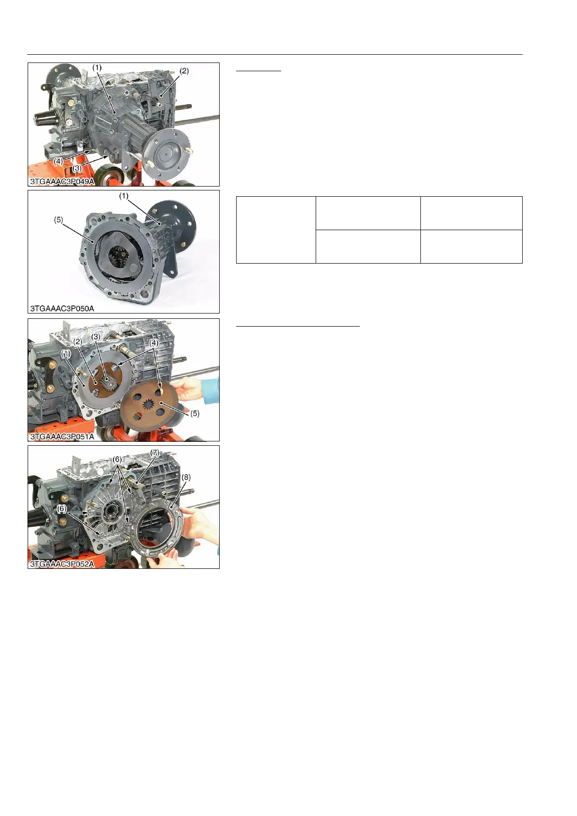
1. Remove the brake stay (2).
2. Remove the setting screw (4) and pull out the lower link pin (3).
3. Place the disassembling stand under the rear axle case.
4. Remove the rear axle mounting screws and nuts, and separate
the rear axle (1).
(When reassembling)
• Apply liquid gasket (Three Bond 1206C or equivalent) to the
joint face of the rear axle case and transmission case.
• Fix the brake plate 2 (5) to the rear axle case (1) with the liquid
gasket.
9Y1211109TRS0039US0
Brake Disc and Brake Cam
1. Remove the brake disc (5), brake shaft (3), brake plate 1 (1) and
brake disc (2).
2. Remove the cam plate (8) and steel balls (6).
3. Remove the brake cam (7).
(When reassembling)
• Apply grease to the steel ball seats. (Do not apply the grease
excessively.)
• Place the brake disc (5) so that the brake disc hole (4) should
be overlapped 50 % or more.
• Apply grease to the O-ring on the brake cam (7).
• Be sure to fix the brake cam (7) and cam plate (8).
9Y1211109TRS0040US0
Tightening torque
Brake stay mounting screw
39.3 to 44.1 N·m
4.0 to 4.5 kgf·m
29.0 to 32.5 lbf·ft
Brake case mounting screw
39.3 to 44.1 N·m
4.0 to 4.5 kgf·m
29.0 to 32.5 lbf·ft
(1) Rear Axle
(2) Brake Stay
(3) Lower Link Pin
(4) Setting Screw
(5) Brake Plate 2
(1) Brake Plate 1
(2) Brake Disc
(3) Brake Shaft
(4) Brake Disc Hole
(5) Brake Disc
(6) Steel Ball
(7) Brake Cam
(8) Cam Plate


 To Next Page