ELECTRICAL SYSTEM
STW34, STW37, STW40, WSM
9-S37
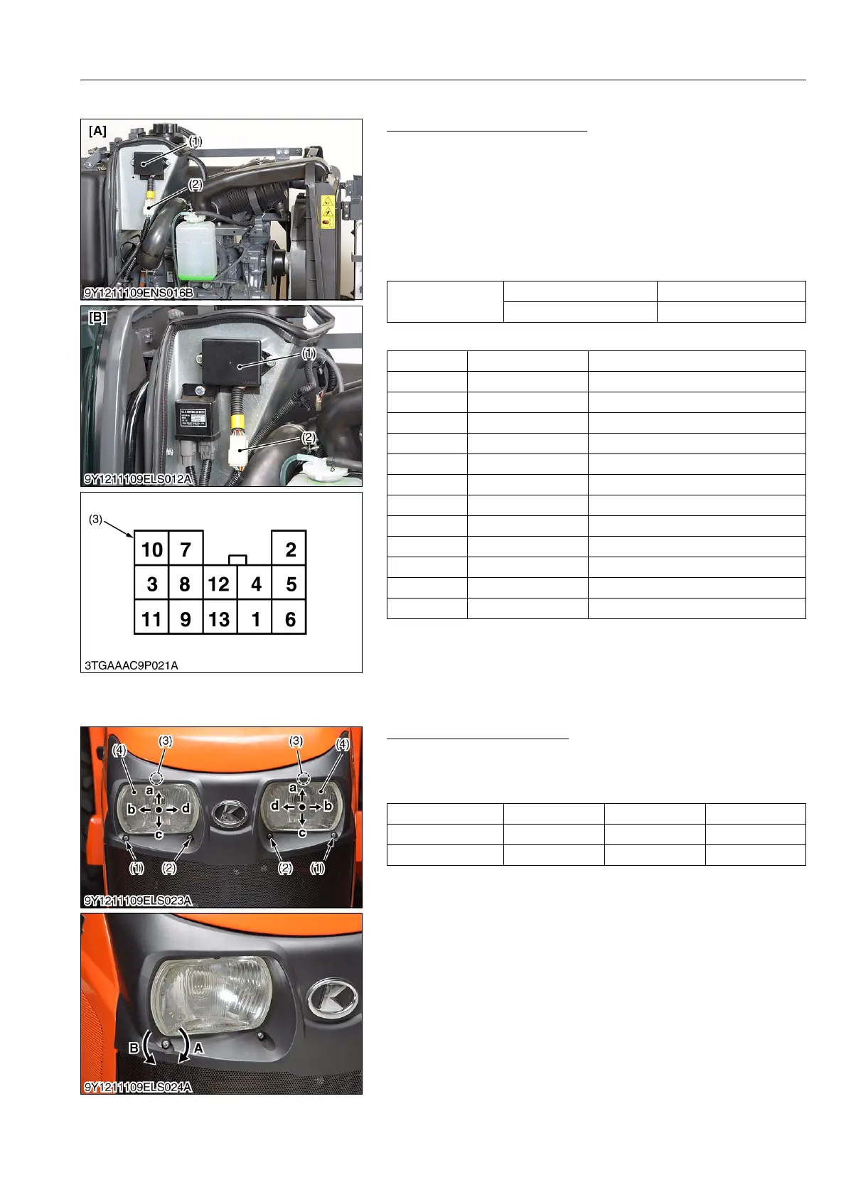
(23) Flasher Unit
Flasher Unit Terminal Voltage
1. Disconnect the battery negative cable, and remove the hood
and side cover.
2. Disconnect the flasher unit connector (2) and connect the
battery ground cable.
3. Measure the voltage with a voltmeter between 12 terminal and
7 terminal, between 13 terminal and 7 terminal.
4. If the voltage differs from the battery voltage, the wiring harness
is faulty.
(Reference)
9Y1211109ELS0067US0
(24) Head Light
Adjustment of Optical Axis
1. Turn the adjustment screws (1), (2) and nuts (3) to the clockwise
or counterclockwise.
2. Regarding the direction of optical axis shown in the table below.
9Y1211109ELS0081US0
Voltage
12 terminal – 7 terminal Approx. battery voltage
4 terminal – 7 terminal Approx. battery voltage
1 0.5 Y Lighting switch
2 0.85 Y Licence Light
3 ––
4 0.85 W/G Main switch (IG)
5 0.5 G Turn signal light (R)
6 0.5 G/R Turn signal light switch (R)
7 0.5 B Ground
8 0.5 Sb Turn signal light (L)
9 0.5 G/Y Turn signal light switch (L)
10 0.5 G/B Trailer
11 0.5 W/L Hazard switch
12 1.25 R/B Battery Voltage
13 ––
(1) Flasher Unit
(2) Flasher Unit Connector
(3) Connector (Harness Side)
[A] ROPS Model
[B] Cabin Model
(1) (2) (3)
Clockwise Inside Outside Up
Counterclockwise Outside Inside Down
(1) Screw
(2) Screw
(3) Nut
(4) Head Light
A: Clockwise
B: Counterclockwise
a: Up
b: Outside
c: Down
d: Inside



 To Next Page