ELECTRICAL SYSTEM
STW34, STW37, STW40, WSM
9-M16
[2] SYSTEM OUTLINE
(General Information for Bi-speed Controller)
• Bi-speed controller (ECU) processes and judges the input signals from the switches and sensors, and sends the
signals to Bi -speed solenoid valves concerned with the bi-speed control system.
• Therefore, Bi-speed controller (ECU) controls the engagement of the hydraulic clutches.
• Instrument panel ECU processes and judges the input signals from the switches and sensors, and sends the
signals to the indicators (Rear PTO indicator, Mid-PTO indicator and Bi-speed indicator) and the display error
code
• All ECU shares information from switches and sensors.
• In the same way, Bi-speed controller (ECU) receives the input signals from switches and sensors. It converts them
to instrument panel ECU with CAN.
(CAN: Controller Area Network)
CAN is the abbreviation for Controller Area Network. CAN forms the area network connected with all ECU.
All information from sensors and switches are shared with all ECU by using CAN.
9Y1211109ELM0017US0
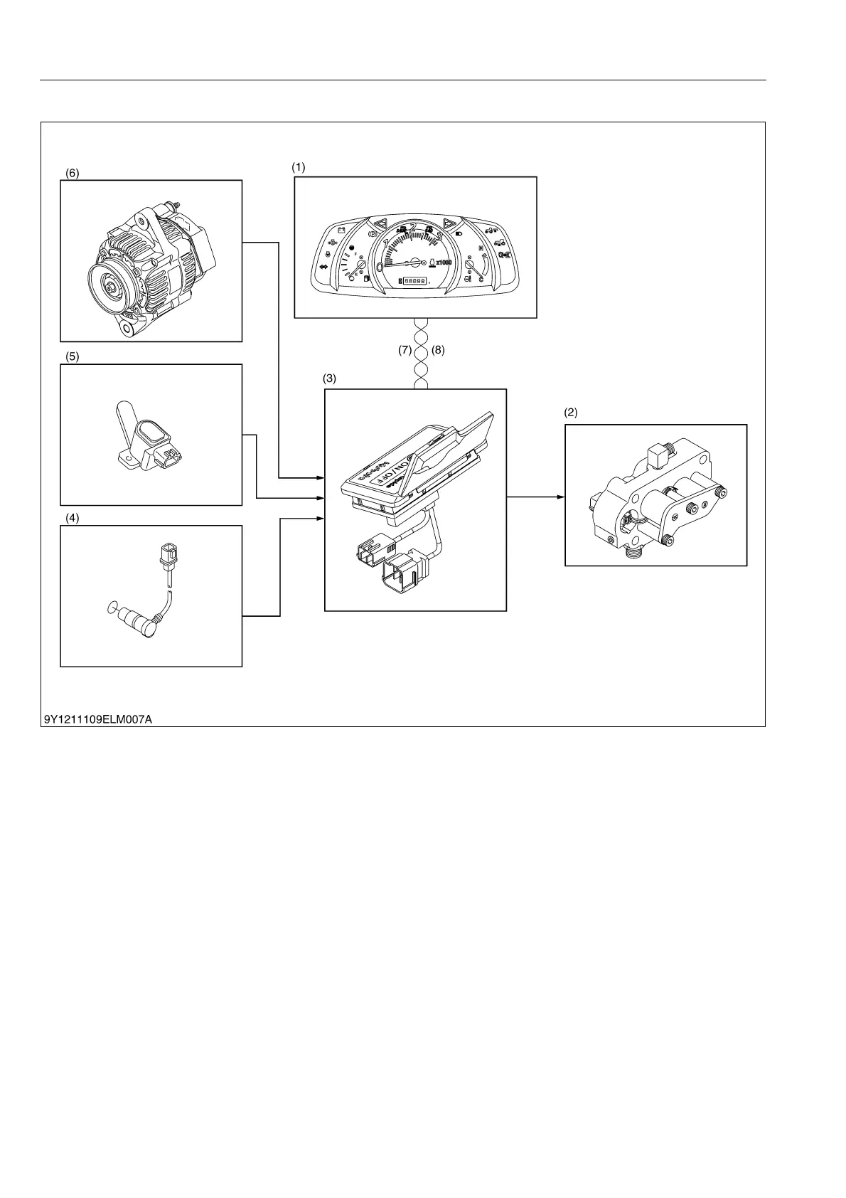
(1) Instrument Panel
(2) Bi-speed Solenoid Valve
(3) Bi-speed Controller
(4) Travelling Speed Sensor
(5) Front Wheel Angle Sensor
(6) Alternator
(7) CAN-L
(8) CAN-H
 Loading...