FRONT AXLE
STW34, STW37, STW40, WSM
6-S7
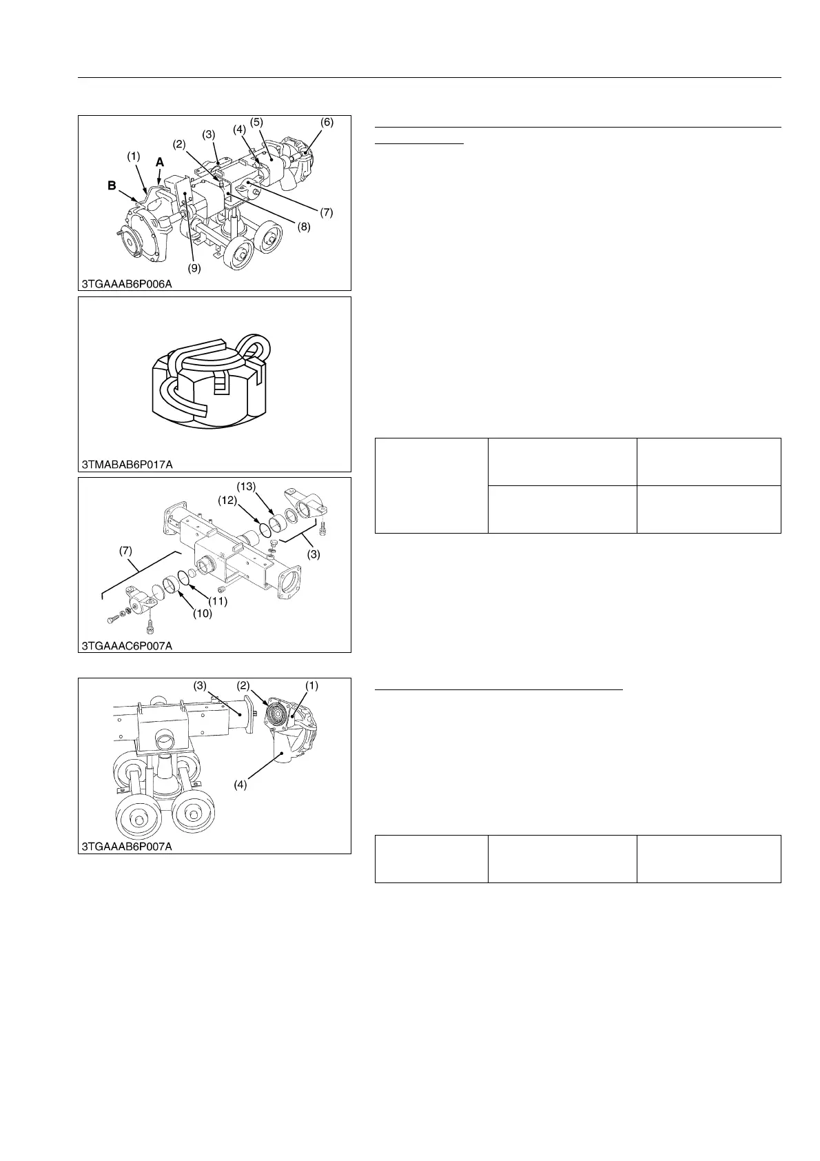
(2) Disassembling Front Axle Assembly
Steering Cylinder, Axle Bracket and Front Wheel Turning
Angle Sensor
1. Remove the slotted nut and remove the both R.H. and L.H.
tie-rod (6).
2. Remove the front axle brackets (3), (7).
3. Remove the cylinder cover (5).
4. Remove the hydraulic connector (2) R.H. or L.H. to slide out the
steering cylinder (8).
5. Remove the steering cylinder mounting reamer screw (4) and
remove the cylinder (8).
6. Remove the front wheel turning angle sensor (9).
(When reassembling)
• Apply grease to the O-rings (11), (12) and bushings (10), (13) of
front axle bracket.
• After tightening the slotted nut to the specified torque, install the
cotter pin as shown in the figure.
• Apply seal tape to thread portion of hydraulic connector.
• Assemble the sensor arm, longer side "A" fix to the bi-speed
sensor as figure.
9Y1211109FAS0010US0
Bevel Gear Case and Front Gear Case
1. Remove the bevel gear case mounting screws.
2. Remove the bevel gear case (1) and front gear case (4) as a unit
from the front axle case (3).
(When reassembling)
• Apply grease to the O-ring (2) and be careful not to damage it.
• Do not interchange right and left bevel gear case assemblies
and right and left gear case assemblies.
• Be sure to fix the turning angle sensor arm holder.
9Y1211109FAS0011US0
Tightening torque
Tie-rod end nut
(Power steering cylinder)
34.3 to 44.1 N·m
3.5 to 4.5 kgf·m
25.3 to 32.5 lbf·ft
Steering cylinder mounting
reamer screw
48.1 to 55.9 N·m
4.9 to 5.7 kgf·m
35.4 to 41.2 lbf·ft
(1) Sensor Arm
(2) Hydraulic Connector
(3) Front Axle Bracket (Rear)
(4) Reamer Screw
(5) Cylinder Cover
(6) Tie-rod
(7) Front Axle Bracket (Front)
(8) Steering Cylinder
(9) Front Wheel Turning Angle Sensor
(10) Bushing
(11) O-ring
(12) O-ring
(13) Bushing
A: Longer Side
B: Shorter Side
Tightening torque
Bevel gear case mounting
screw
77.5 to 90.2 N·m
7.9 to 9.2 kgf·m
57.1 to 66.5 lbf·ft
(1) Bevel Gear Case
(2) O-ring
(3) Front Axle Case
(4) Front Gear Case