ENGINE
STW34, STW37, STW40, WSM
1-S74
Oil Clearance between Crankpin and Crankpin Bearing
1. Clean the crankpin and crankpin bearing.
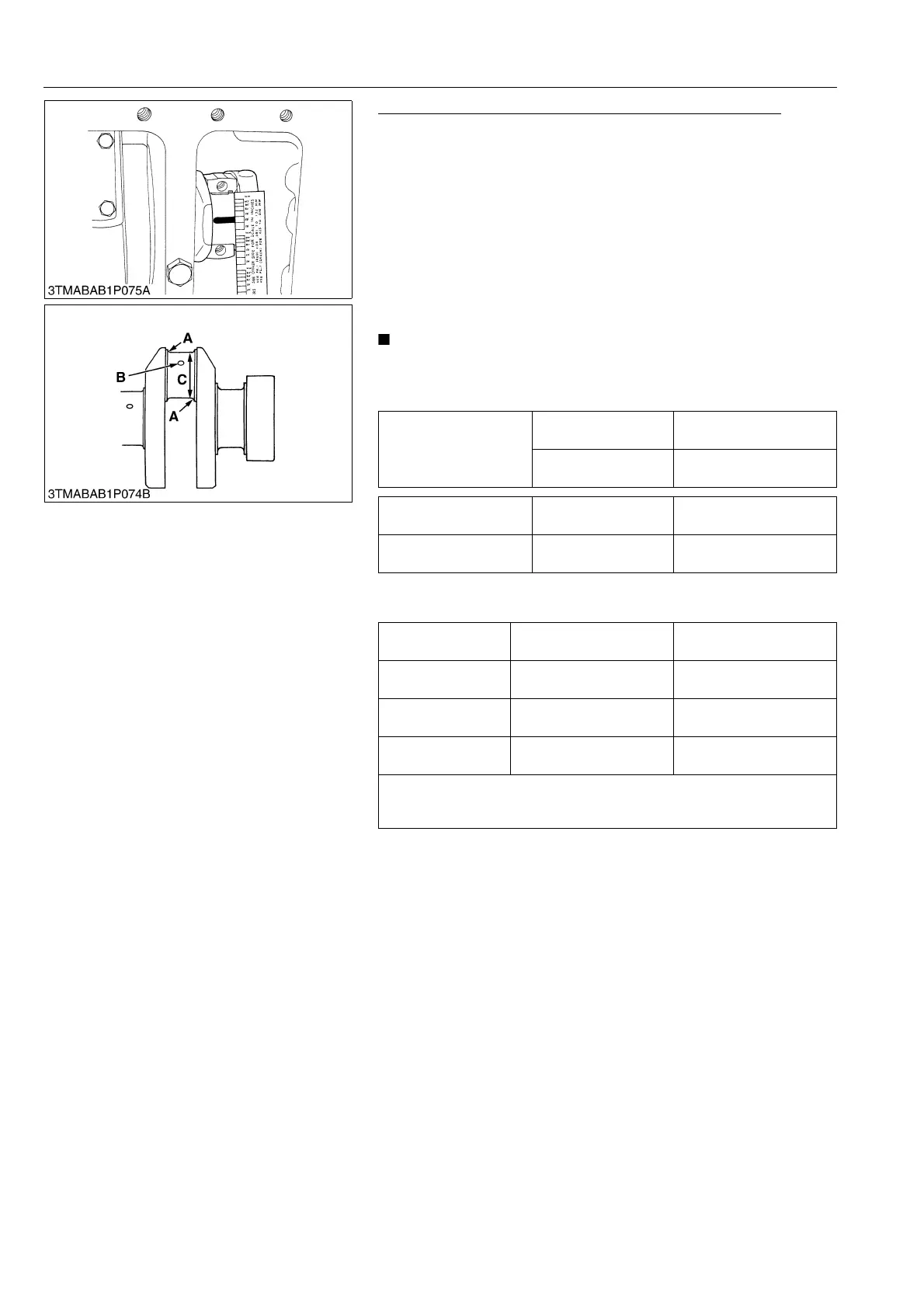
2. Put a strip of plastigauge on the center of the crankpin.
3. Install the connecting rod cap and tighten the connecting rod
screws to the specified torque, and remove the cap again.
4. Measure the amount of the flattening with the scale, and get the
oil clearance.
5. If the oil clearance exceeds the allowable limit, replace the
crankpin bearing.
6. If the same size bearing is useless because of the crankpin
wear, replace it with an undersize one referring to the table and
figure.
• Never insert the plastigauge into the crankpin oil hole.
• Be sure not to move the crankshaft while the connecting
rod screws are tightened.
(Reference)
• Undersize dimensions of crankpin
9Y1211109ENS0121US0
Oil clearance between
crankpin and crankpin
bearing
Factory specification
0.025 to 0.087 mm
0.00099 to 0.0034 in.
Allowable limit
0.2 mm
0.0079 in.
Crankpin O.D. Factory specification
46.959 to 46.975 mm
1.8488 to 1.8494 in.
Crankpin bearing I.D. Factory specification
47.000 to 47.046 mm
1.8504 to 1.8522 in.
Undersize
0.2 mm
0.008 in.
0.4 mm
0.016 in.
Dimension A
3.3 to 3.7 mm radius
0.13 to 0.14 in. radius
3.3 to 3.7 mm radius
0.13 to 0.14 in. radius
Dimension B
1.0 to 1.5 mm radius
0.040 to 0.059 in. radius
1.0 to 1.5 mm radius
0.040 to 0.059 in. radius
Dimension C
46.759 to 46.775 mm dia.
1.8409 to 1.8415 in. dia.
46.559 to 46.575 mm dia.
1.8331 to 1.8336 in. dia.
The crankpin must be fine-finished to higher than = 0.4S
*Holes to be de-burred and edges rounded with 1.0 to 1.5 mm (0.040 to
0.059 in.) relief.


 To Next Page