ENGINE
STW34, STW37, STW40, WSM
1-S76
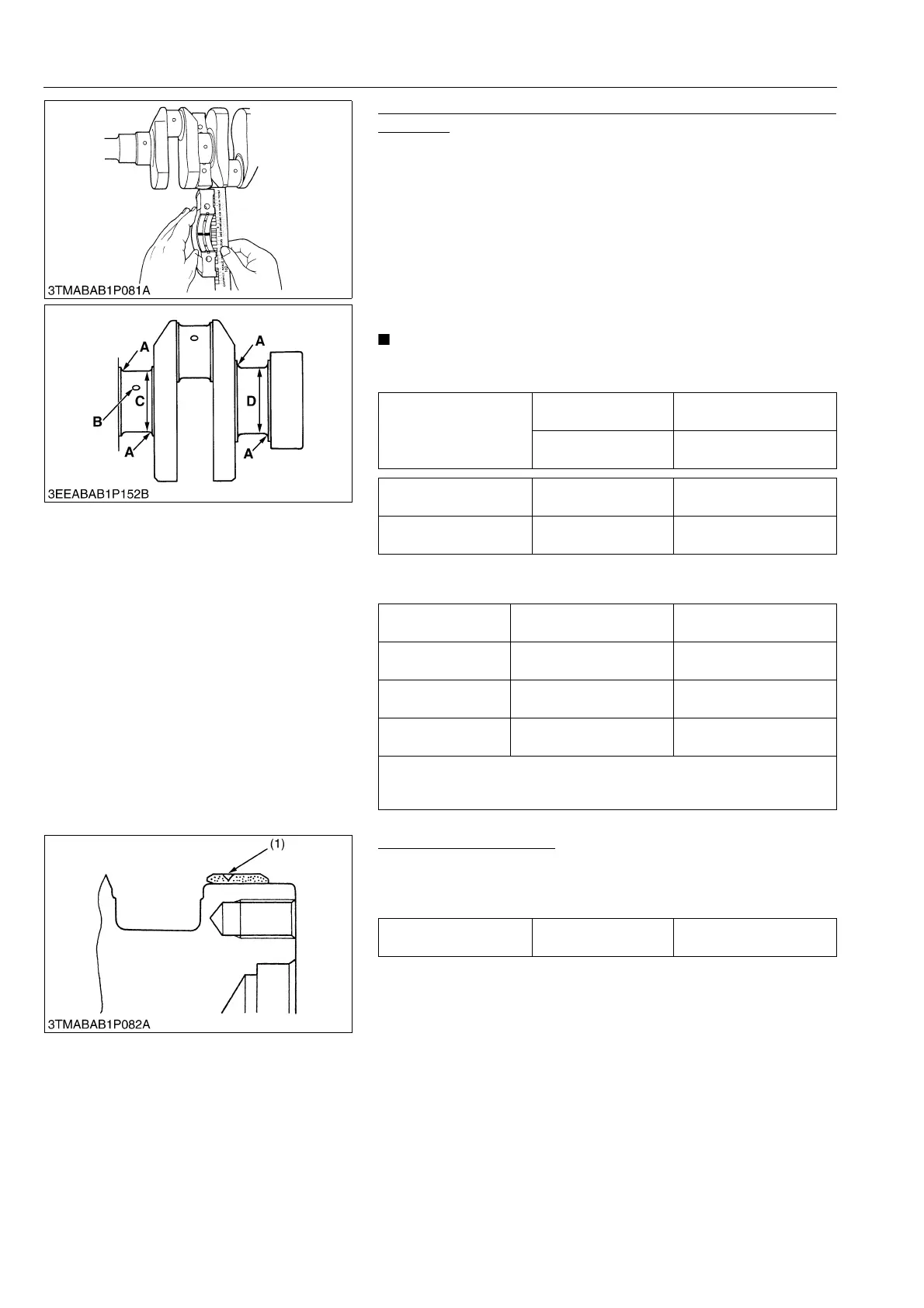
Oil Clearance between Crankshaft Journal and Crankshaft
Bearing 2
1. Put a strip of plastigauge on the centre of the journal.
2. Install the bearing case and tighten the bearing case screws 1
to the specified torque, and remove the bearing case again.
3. Measure the amount of the flattening with the scale and get the
oil clearance.
4. If the clearance exceeds the allowable limit, replace the
crankshaft bearing 2.
5. If the same size bearing is useless because of the crankshaft
journal wear, replace it with an undersize one referring to the
table and figure.
• Be sure not to move the crankshaft while the bearing case
screws are tightened.
(Reference)
• Undersize dimensions of crankshaft journal
9Y1211109ENS0124US0
Crankshaft Sleeve Wear
1. Check the wear on the crankshaft sleeve (1).
2. If the wear exceeds the allowable limit or when the engine oil
leaks, replace the crankshaft sleeve.
9Y1211109ENS0125US0
Oil clearance between
crankshaft and
crankshaft bearing 2
Factory specification
0.0400 to 0.104 mm
0.00158 to 0.00409 in.
Allowable limit
0.20 mm
0.0079 in.
Crankshaft O.D. Factory specification
59.921 to 59.940 mm
2.3591 to 2.3598 in.
Crankshaft bearing 2 I.D. Factory specification
59.980 to 60.025 mm
2.3615 to 2.3631 in.
Undersize
0.2 mm
0.008 in.
0.4 mm
0.016 in.
Dimension A
2.8 to 3.2 mm radius
0.11 to 0.12 in. radius
2.8 to 3.2 mm radius
0.11 to 0.12 in. radius
Dimension B
1.0 to 1.5 mm radius
0.040 to 0.059 in. radius
1.0 to 1.5 mm radius
0.040 to 0.059 in. radius
Dimension C, D
59.721 to 59.740 mm dia.
2.3513 to 2.3519 in. dia.
59.521 to 59.540 mm dia.
2.3434 to 2.3440 in. dia.
The crankshaft journal must be fine-finished to higher than = 0.4S
*Holes to be de-burred and edges rounded with 1.0 to 1.5 mm (0.040 to
0.059 in.) relief.
Wear of sleeve Allowable limit
0.1 mm
0.0039 in.
(1) Crankshaft Sleeve


 To Next Page