HYDRAULIC SYSTEM
STW34, STW37, STW40, WSM
8-M14
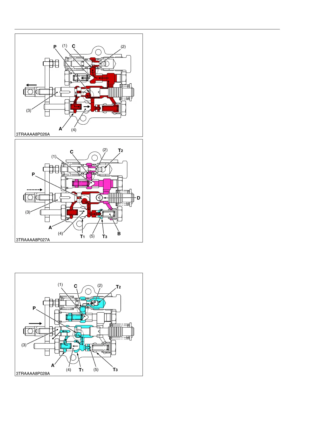
Lifting
When the control lever is moved to "UP" position,
spool (3) is pulled by the spool operating lever, forming
a circuit with the P port and chamber A.
The pressurized oil thus flows into the chamber A
and closes unload poppet 1 (4).
The pressure in the circuit slowly rises, pushing open
poppet 1 (1), and the hydraulic oil flows into the hydraulic
cylinder from the C port, lifting the implement.
9Y1211109HYM0019US0
Lifting to Neutral (Acting the shockless
mechanism)
In returning from Lifting to Neutral, the spool (3) is
pushed back to the arrow-mark direction. When the
Neutral position comes near, the groove part D of the
spool (3) makes the pressure difference at the P port and
C port. Therefore, the poppet 1 (1) gradually closes, and
absorbs any shock at lifting stop. In that case, since oil is
remained in the chamber A of the unload poppet 1 (4)
and closes. However, the unload poppet 2 (5) opens
because of low pressure in chamber B, and then the oil
from the pump returns to the transmission case through
T
3
port until unload poppet 1 (4) opens.
9Y1211109HYM0020US0
Lowering
When the control lever is moved to "DOWN"
position, spool (3) moves to arrow-mark direction, and
pushes the poppet 2 (2). If forms a circuit with the C port
and T
2
port.
The oil in the hydraulic cylinder is forced out by the
weight of the implement, and returns to the tank through
the C port and T
2
port, lowering the implement. The
pressurized oil pushes open unload poppet 1 (4) and
returns to the tank from T
1
port.
Floating
When the control lever is lowest position, spool (3)
and poppet 2 (2) keeps same as lowering position. The
hydraulic cylinder is unloading condition. Therefore
pressurized oil pushes open unload poppet 1 (4) and
returns to tank.
9Y1211109HYM0021US0
(1) Poppet 1
(2) Poppet 2
(3) Spool
(4) Unload Poppet 1
P: Pump Port
C: Cylinder Port
A: Chamber A
(1) Poppet 1
(2) Poppet 2
(3) Spool
(4) Unload Poppet 1
(5) Unload Poppet 2
P: Pump Port
C: Cylinder Port
A: Chamber A
B: Chamber B
D: Groove 1
T
1
:Tank Port 1
T
2
:Tank Port 2
T
3
:Tank Port 3
(1) Poppet 1
(2) Poppet 2
(3) Spool
(4) Unload Poppet 1
(5) Unload Poppet 2
P: Pump Port
C: Cylinder Port
T
1
:Tank Port 1
T
2
:Tank Port 2
T
3
:Tank Port 3


 To Next Page