HYDRAULIC SYSTEM
STW34, STW37, STW40, WSM
8-S12
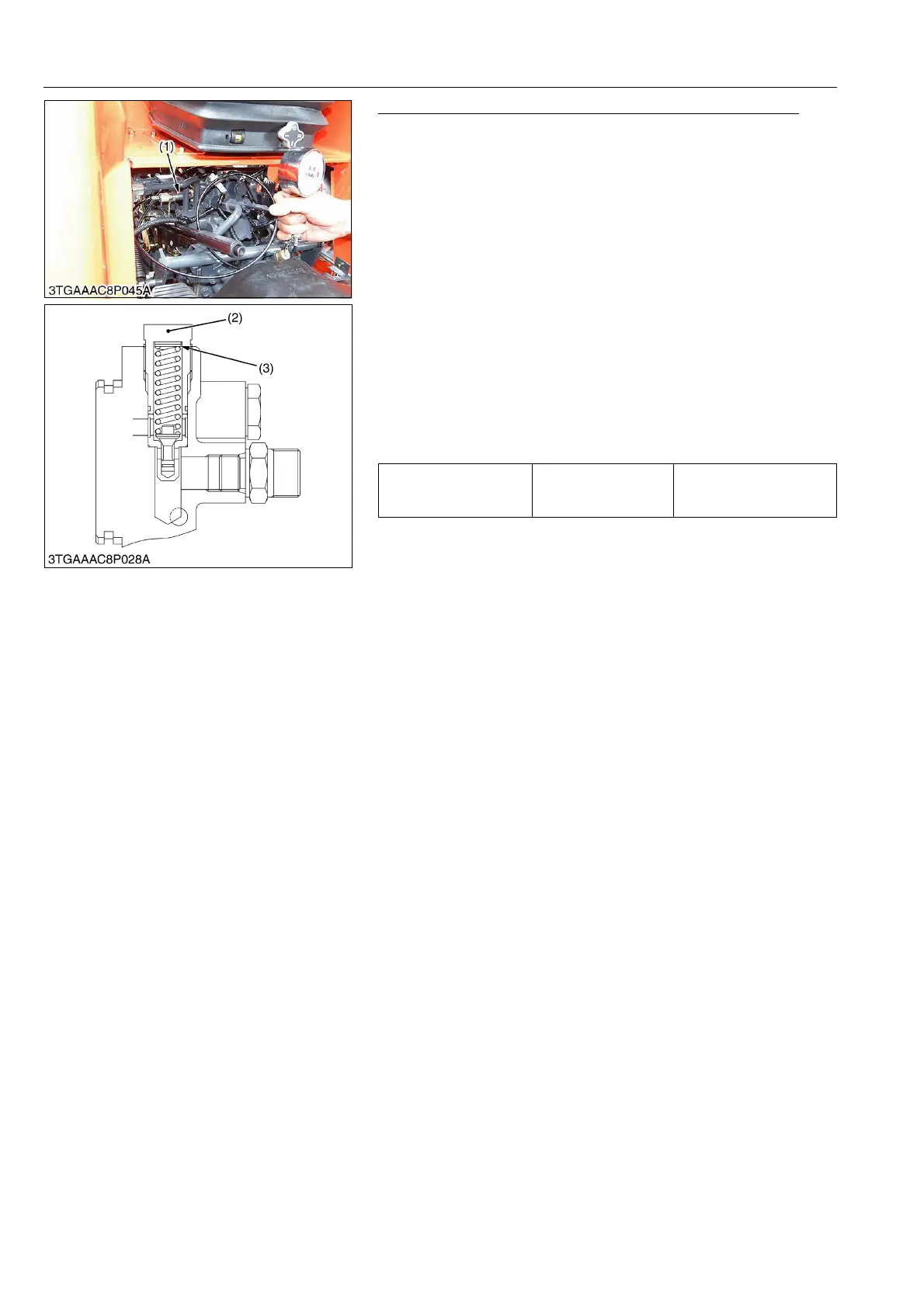
Relief Valve Setting Pressure Test Using Pressure Tester
1. Start the engine and move the position control lever to the
maximum raising position.
2. Turn the feedback rod adjusting nut and lock nut until the relief
valve begins to be operated. (Refer to 8-S11 "Adjusting
Feedback Rod".).
3. Move the position control lever to the lowest position and stop
the engine.
4. Remove the plug of hydraulic cylinder cover and install the
adaptor 4. Then connect the cable (Code No.: 07916-50331)
and pressure gauge (Code No.: 07916-50322) to adaptor 4.
5. Start the engine and set the engine speed at maximum.
6. Move the position control lever to the maximum raising position
and read the pressure when the relief valve functions.
7. Stop the engine.
8. If the pressure is not within the factory specification, remove the
relief valve plug (2) and adjust with adjusting shims (3).
9. After the relief valve setting pressure test, adjust the feedback
control rod. (See page 8-S11.)
Condition
• Engine speed:
Maximum
• Oil temperature:
40 to 60 °C (104 to 140 °F)
(Reference)
• Adaptor 4 is included in engine oil pressure tester (Code No.:
07916-32032).
• Thickness of shim (3):
0.1 mm (0.0039 in.)
0.2 mm (0.0078 in.)
0.4 mm (0.0157 in.)
• Pressure change per 0.1 mm (0.0039 in.) shim:
Approx. 264.8 kPa (2.7 kgf/cm
2
, 38.4 psi)
9Y1211109HYS0012US0
Relief valve setting
pressure
Factory specification
16.7 to 17.2 MPa
170 to 175 kgf/cm
2
2420 to 2480 psi
(1) Adaptor 4
(2) Relief Valve Plug
(3) Shim


 To Next Page