ENGINE
STW34, STW37, STW40, WSM
1-S11
• For "*" marked screws, bolts and nuts on the table, apply engine oil to their threads and seats before
tightening.
• The letter "M" in Size × Pitch means that the screw, bolt or nut dimension stands for metric. The size is
the nominal outside diameter in mm of the threads. The pitch is the nominal distance in mm between two
threads.
9Y1211109ENS0003US0
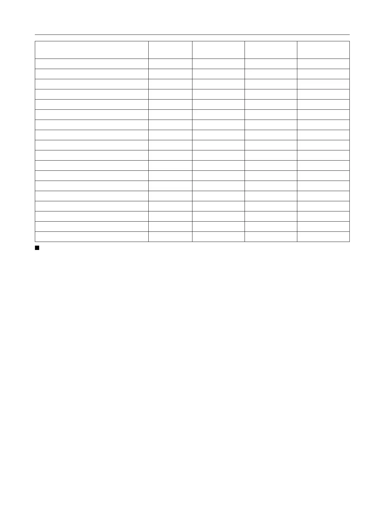
Item
Dimension ×
Pitch
N·m kgf·m lbf·ft
Cylinder head cover screw M6 × 1.0 6.87 to 11.2 0.700 to 1.15 5.07 to 8.31
*Cylinder head screw M11 × 1.25 93.2 to 98.0 9.50 to 10.0 68.8 to 72.3
*Main bearing case screw 1 M9 × 1.25 46 to 50 4.7 to 5.2 34 to 37
*Main bearing case screw 2 M10 × 1.25 69 to 73 7.0 to 7.5 51 to 54
*Flywheel screw M12 × 1.25 98.1 to 107 10.0 to 11.0 72.4 to 79.5
*Connecting rod screw M8 × 1.0 41 to 45 4.1 to 4.6 30 to 33
*Rocker arm bracket screw M8 × 1.25 24 to 27 2.4 to 2.8 18 to 20
*Idle gear shaft screw M8 × 1.25 24 to 27 2.4 to 2.8 18 to 20
Fan drive pulley mounting nut M30 × 1.5 138 to 156 14.0 to 16.0 102 to 115
*Bearing case cover mounting screw M8 × 1.25 24 to 27 2.4 to 2.8 18 to 20
Glow plug M10 × 1.25 20 to 24 2.0 to 2.5 15 to 18
Nozzle holder assembly M20 × 1.5 49 to 68 5.0 to 7.0 37 to 50
Nozzle holder – 35 to 39 3.5 to 4.0 26 to 28
Oil pressure switch R1/8 15 to 19 1.5 to 2.0 11 to 14
Injection pipe retaining nut M12 × 1.5 25 to 34 2.5 to 3.5 18 to 25
Overflow pipe assembly retaining nut M12 × 1.5 20 to 24 2.0 to 2.5 15 to 18
Camshaft set screw M8 × 1.25 24 to 27 2.4 to 2.8 18 to 20
Hi-idling body M14 × 1.0 45 to 49 4.5 to 5.0 33 to 36


 To Next Page