Page | 7
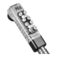
4. Verify that the Flowmeter is functioning:
a. Select MACHINE INFO. See Figure 8a.
b. Open product tap and verify that the TOTAL DISPENSED and DISPENSE RATE readings are changing. See
Figure 8b.
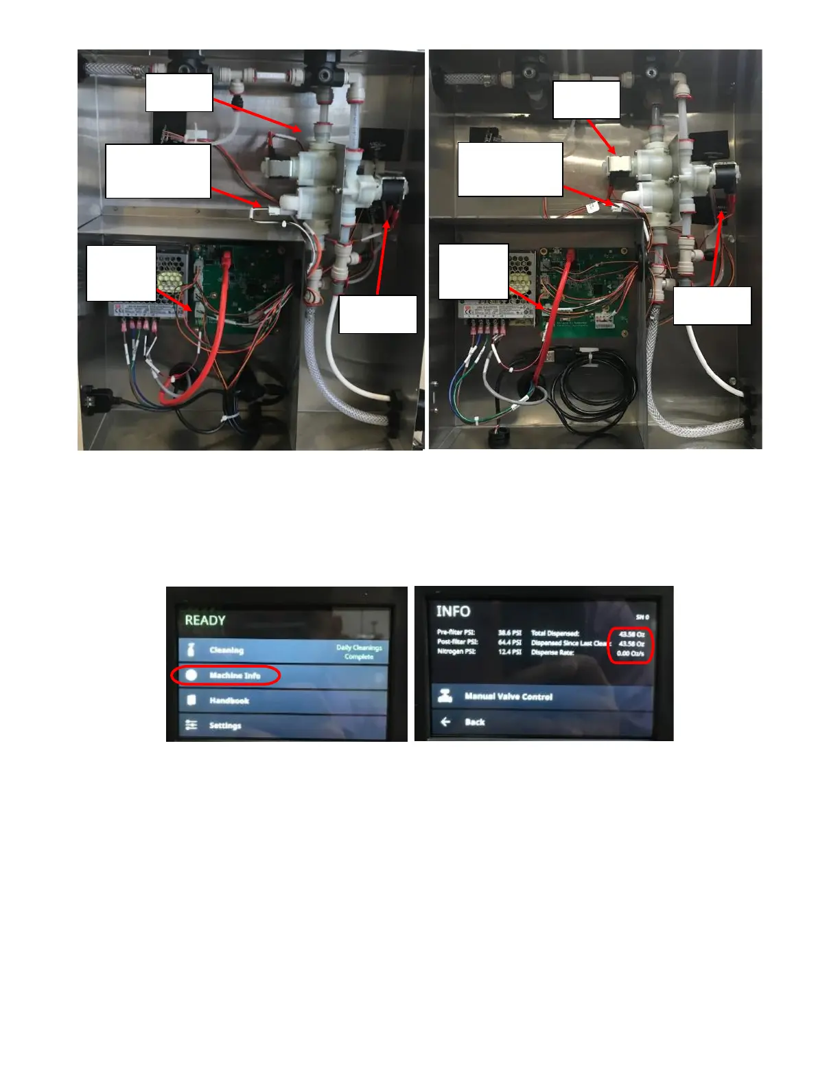
5. If Flowmeter is not reading on the screen, verify that the Flowmeter Harness is correct. The three wires (White,
Black, and Gray) should be in the same sequence on both ends of the connector. If the wire color sequence
differs on both connectors are not the same, replace the Flowmeter Harness and verify the functionality of the
Flowmeter again.
6. If Flowmeter is still not reading, update the software. Refer to Appendix E: Software Update Instructions.
7. If Flowmeter is not reading on the screen after a software update, replace the Flowmeter Solenoid Module and
verify the functionality of the Flowmeter again. Refer to Appendix F: Flowmeter/Solenoid Module Replacement
for procedure.
8. Verify that the Flowmeter is functioning as seen in step 4 above. If the TOTAL DISPENSED AND DISPENSE RATE
readings are changing, verify the problem is fixed by running the cleaning cycle again.
9. If updating the software, Solenoid Harness is plugged in correctly, and replacing the Flowmeter Harness and
Flowmeter Solenoid assembly does not resolve the issue, the problem is with the PCB; replace the PCB.