Page | 63
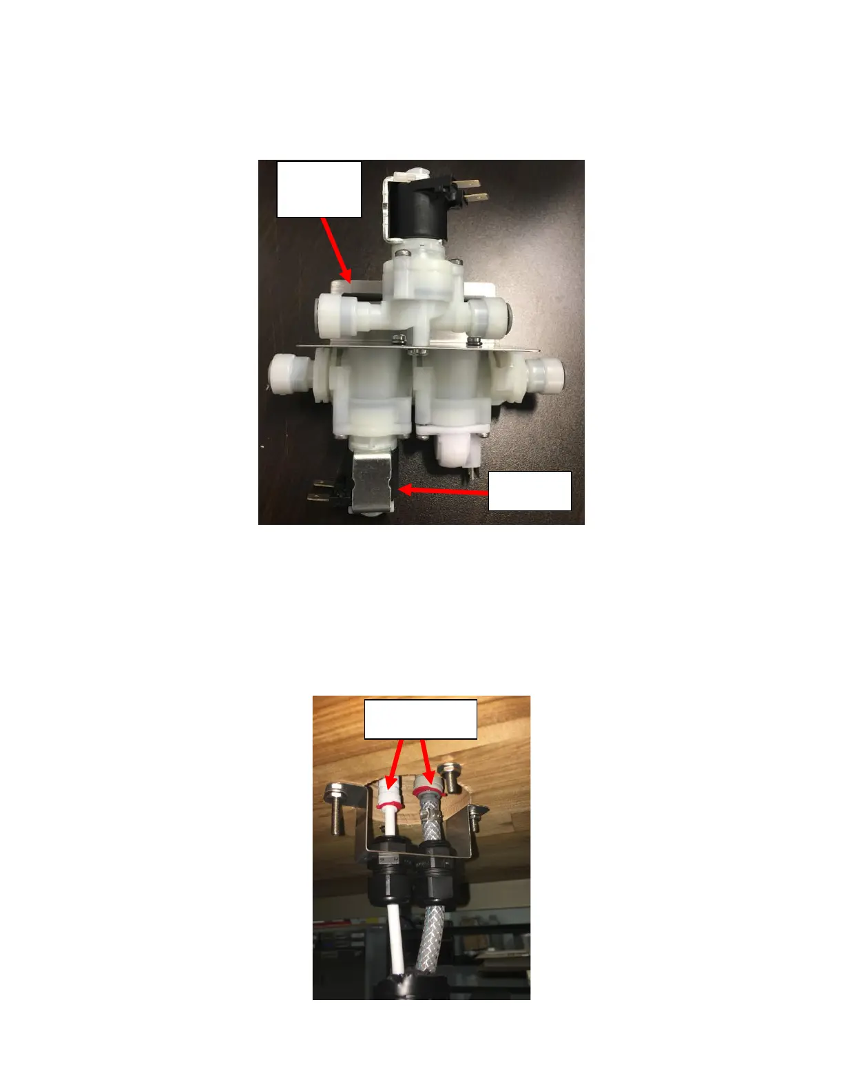
7. Replace the Solenoid Flowmeter Module if it is still functional or replace if necessary. Remember to reinstall the split
washer removed when reinstalling the new Solenoid Flowmeter Module to prevent it from getting damaged. The
Flowmeter Solenoid Module should be installed so that the Solenoid is on the LEFT with the Bracket Flange facing
away from you. See Figure G6.
8. Replace the rest of the fittings/tubing in the reverse order of that it was removed in.
Appendix H: Disassembling the Tower
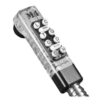
1. Identify the Leak. If it is from the connections made from the Insulated Bundle, the tower does not need to be
disassembled. Simply push the connections in further to engage the O-Ring inside the John Guest Fittings to seal.
See Figure H1.