Page | 6
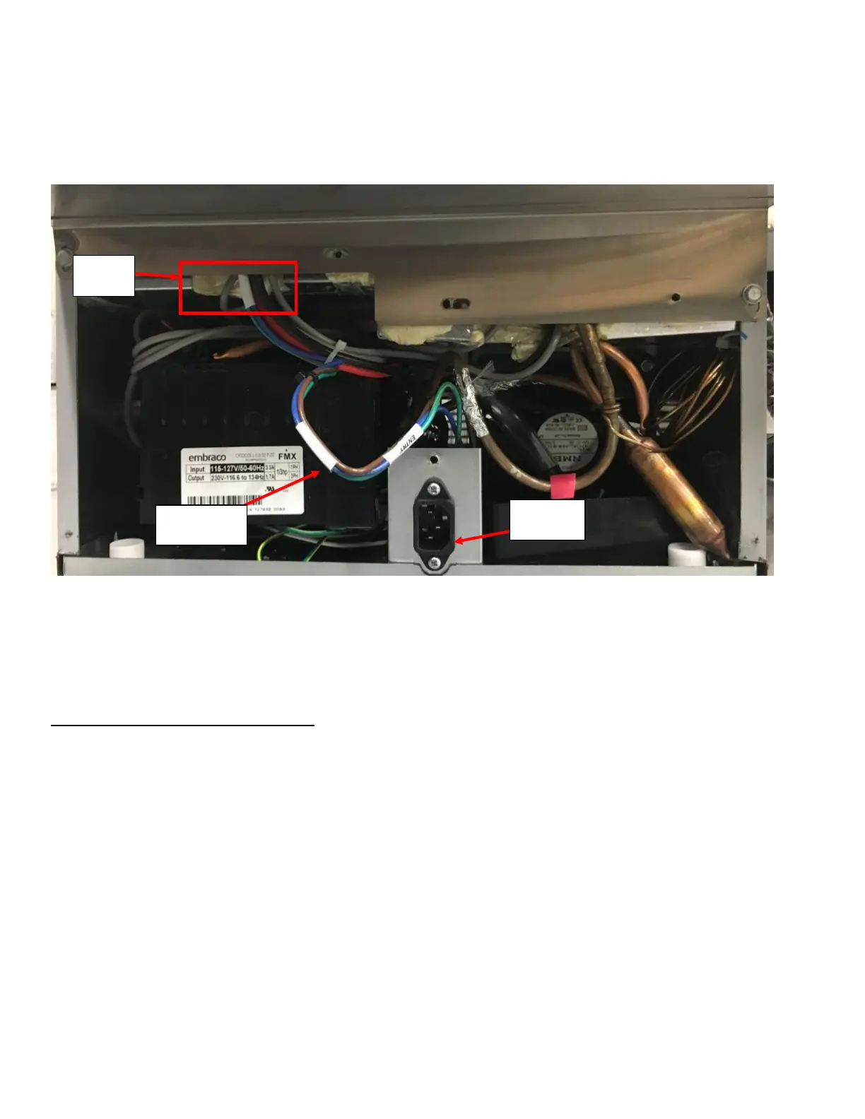
e. If the input does not have ~120VAC, remove the Bottom Rear Panel using 5/16-inch Hex Socket Drive to
access the High Voltage Supply Harness (Can be identified by its Blue, Brown, and Green/Yellow wire
strands). Verify that the Harness is not damaged (pinched, pierced, or cut) through the length of the harness
from the black power plug through the Foam Channel under the Rear Enclosure. See Figure 6. You may have
to remove the Black Power Plug to fully inspect the harness. Refer to Appendix C: JoeTap NITCOM Wiring
Diagram for full wiring diagram. Replace the High Voltage Power Supply if damaged.
3. If all the wires are plugged correctly (and not damaged) and the screen is the only electronic component that
does not have power (PCB will have LED lights on), verify that the ethernet cable is undamaged. Bypassing the
installed ethernet cable with a known/functioning ethernet cable would be easiest way to check.
4. If ethernet cable is functional and the screen is getting the power, then replace the screen.
Symptom 2: Unit Stuck in Cleaning Cycle:
1. Remove Rear Enclosure Cover panel by removing the four screws holding it to the Rear Enclosure (two on either
side).
2. Verify that the Solenoid Harness is plugged in correctly. Refer to Appendix C: JoeTap NITCOM Wiring Diagram
for full wiring diagram. The BEVERAGE SOLENOID should have the BLUE and ORANGE quick connects attached
and the NITROGEN SOLENOID should have the BROWN and ORANGE quick connects attached. See Figure 7a and
Figure 7b.
3. Identify the Flow Meter and verify it is plugged in on both ends. One end into the flowmeter, the other on the
PCB. See Figure 7a and Figure 7b. Also verify all other harnesses inside the Rear Enclosure are connected in
proper locations. Refer to Appendix C: JoeTap NITCOM Wiring Diagram for full wiring diagram.