Page | 5
2. If the Display Power Supply Harness is connected and undamaged, verify if the PCB is also not receiving power
(LED lights on the PCB will be lit if it is working):
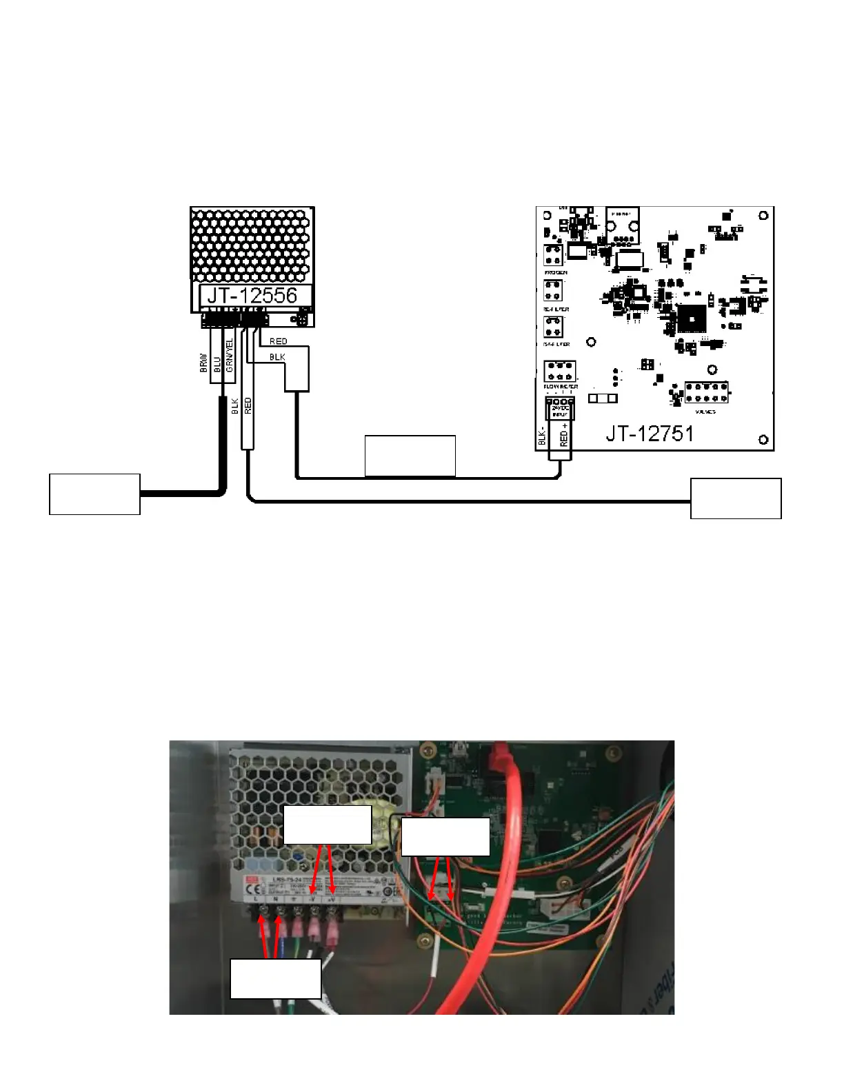
a. If PCB is NOT receiving power, verify the rest of the connections to the Power Supply seen in Figure 4. The
Brown Wire from the High Voltage Power Supply should be connected to L socket on the Power Supply. The
Blue Wire from the High Voltage Power Supply should be connected to the N socket on the Power Supply.
The Green Wire from the High Voltage Power Supply should be connected to the Ground Socket in the
Power Supply.
b. If the PCB lights are off, a DVOM can also be used to verify that the Power Supply output (-V and +V) have a
24VDC output. See Figure 5.
c. Verify the power input terminal on the PCB itself. If there is power at the Power Supply Output but not at
the PCB, the harness is damaged and needs to be replaced See Figure 5.
d. If the Power Supply output does not have power, check the Power Supply input by probing between the L
and N terminals on the Power Supply. If the reading between the L and N terminals is at wall
output(115VAC-127VAC) but the output has no voltage, the Power Supply is damaged and needs to be
replaced. See Figure 5.