Page | 76
fittings. Cut cable tie holding the Pressure Transducer PCB in place on insulation pads if needed (remember to install
the cable tie back in place when done so PCB is not on bare metal).
7. Swap the Pressure Transducers.
8. Turn on the Nitrogen Supply and let the system pressurize.
9. Note the Pressure Reading with that noted in STEP 2. Compare the pressure readings and verify that the pressure
readings have swapped and are close to original readings. If the difference is negligible, the pressure transducer is
functional. See Figure I3 for location of each reading.
10. If the difference is substantial (more than 2psi), replace the pressure transducer. Retest the new pressure
transducer.
11. Install the Pressure Transducers in its original locations. Secure the Pressure Transducer PCB’s onto the Insulation
Foam and secure with a Cable Tie.
METHOD 2: Use Nitrogen Supply Pressure Regulator as Control:
1. Use this method if multiple Pressure Transducers are suspected of damage/malfunction and the Nitrogen Supply has
a Pressure Gauge that can be easily accessed and read.
2. Locate the Nitrogen Supply. Change the Nitrogen Supply output in the 20psi-25psi range and note the pressure
reading. If the Pressure Regulator at the Nitrogen Supply is not self-relieving, then you will have to depressurize the
system to change the pressure. Turn off the Nitrogen Supply and open the faucet handle to release pressure to
depressurize. Note the Pressure Reading at the Nitrogen Supply.
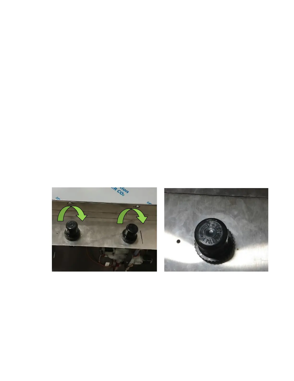
3. Remove the Regulator Cover and turn the Pressure Regulator Knobs and turn them to the max pressure. See Figure
I4 and Figure I5.
4. Connect the Gas Disconnect and Liquid Disconnect inside the refrigerated compartment with an empty Keg.
5. Allow the system to pressurize.
6. Note the pressure reading reported on the Touch Screen. Navigate to Machine Info from the home screen to see the
pressure reading on the Touch Screen. See Figure I6 and Figure I7.