Page | 78
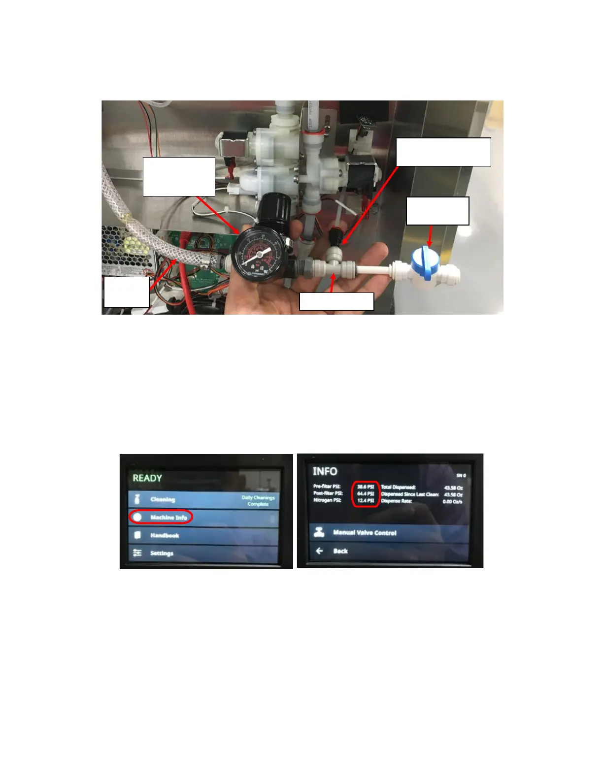
5. Connect the Pressure Transducer to a known pressure (Below 60PSI) and compare the pressure reading with the
known pressure. The stem on the Black Push-to-connect fitting is 0.25” so you will need a gas supply with a 0.25”
Female Push-to-connect output. Ensure you have a way to release the pressure such as a Tee-Fitting with one
output connected to a valve and another to the Pressure Transducer. See Figure I9.
6. Once connected, verify that the pressure reported on the Touch Screen is approximately the same as that of the
known/controlled pressure:
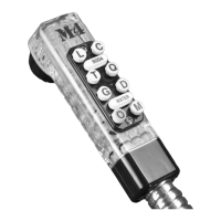
7. Navigate to Machine Info from the home screen to see the pressure reading on the Touch Screen. See Figure I10
and Figure I11.
8. Compare the pressure reading of the known pressure to the pressure reading on the touch screen. If the difference
is negligible, the pressure transducer is functional. See Figure I8 for location of each reading.
9. If the difference is substantial (more than 2psi), replace the pressure transducer.
10. Secure the Pressure Transducer PCB’s onto the Insulation Foam and secure with a Cable Tie.
Figure I11: Machine Info Screen with Pre-Filter,
Post-Filter, and Nitrogen Pressure Circled.