Page | 9
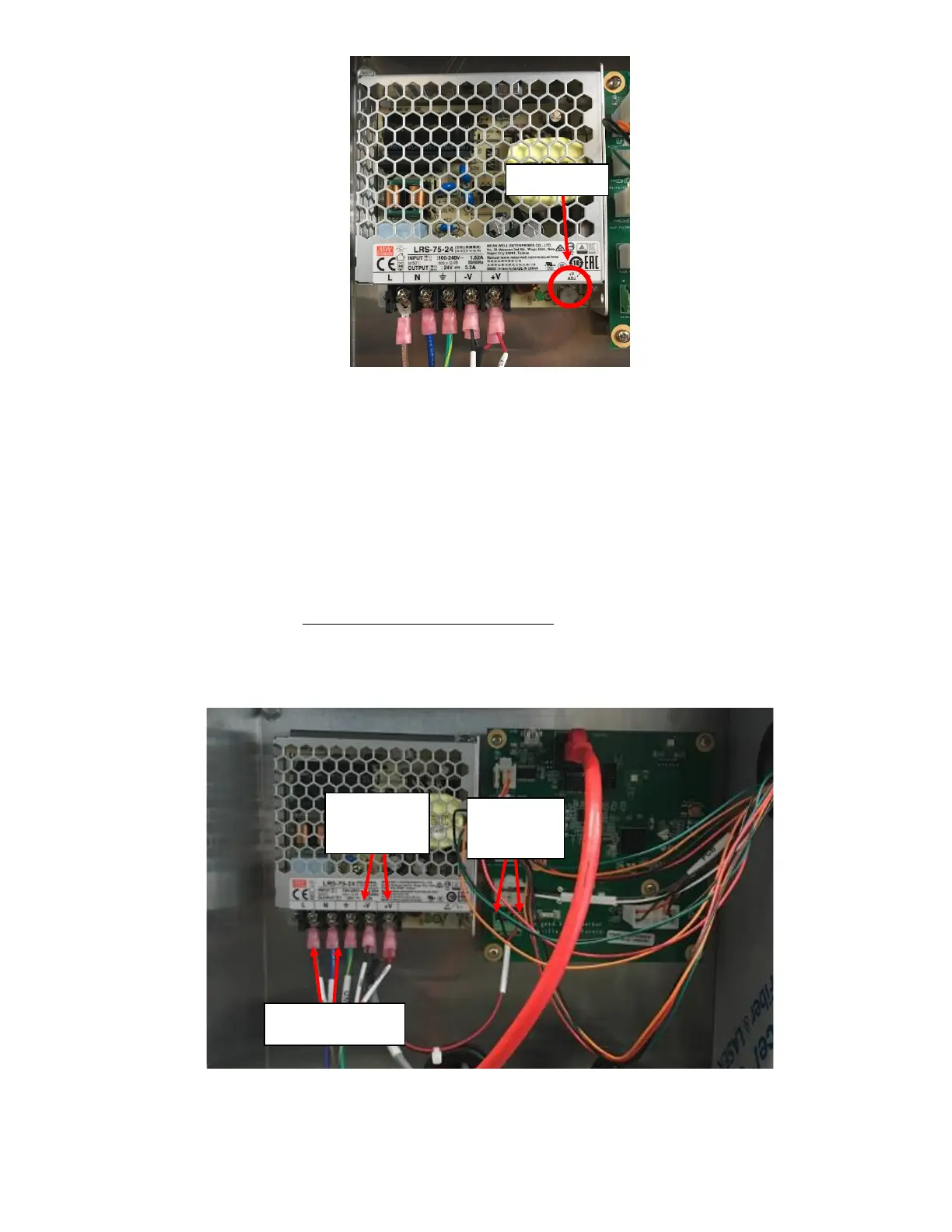
3. If the voltage does not change by use of the potentiometer on the power supply, use a DVOM to check the
voltage output at the Power Supply (-V and +V) to verify it is at 24VDC. See Figure 15. Follow the harness to the
board and verify that the PCB is also getting 24VDC. See Figure 15.
a. If the voltage output on the DVOM is approximately at 24VDC, the issue is with the PCB or the software,
update the software. Refer to Appendix E: Software Update Instructions. If a software update does not
resolve the issue, replace the PCB.
b. If the voltage output on the DVOM is not at approximately 24VDC, the Power Supply may be damaged and
needs to get replaced. Verify the input is getting approximately 120VAC with use of DVOM and follow the
High Voltage Power Harness to ensure it is not damaged if input does not have correct voltage coming in.
See Figure 15. Refer to Symptom 1: Screen Blackout Step 2 to verify the Power Supply is malfunctioning and
replace if necessary.
c. If board is verified to be getting correct voltage and is still displaying INVALID VOLTAGE error, the problem is
with the PCB; replace the PCB.