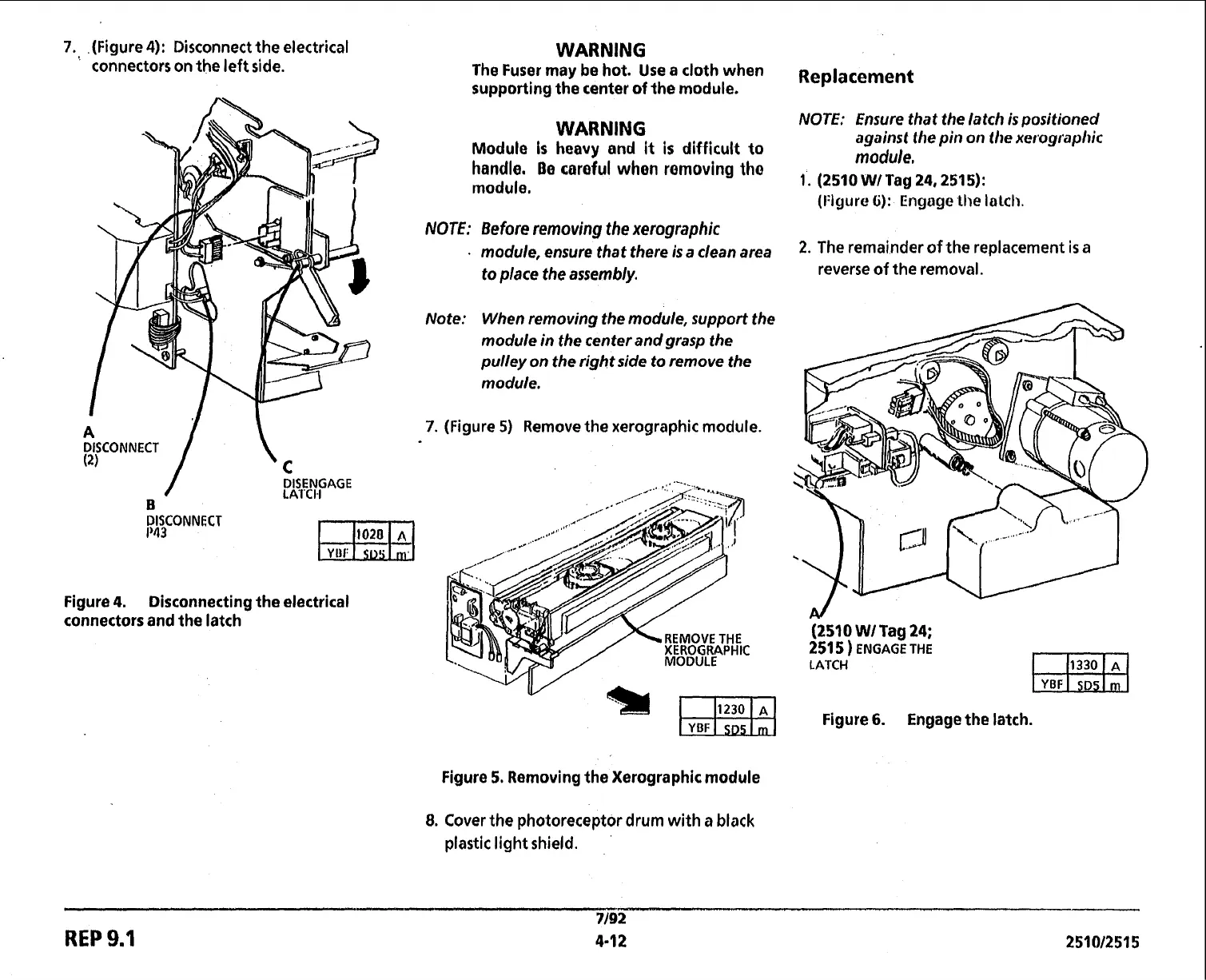
7.
.(Figure
4):
Disconnect the electrical
connectors
on
the left side.
WARNING
The Fuser may be hot. Use a cloth when
~~~l~~~~~~t
supporting the center of the module.
WARNING
NOTE: Ensure that the latch is positioned
against the pin on the xerographic
Module
is
heavy
and
it
is
difficult
to
module,
handle. Be careful when removing tho
,.
(2510
WITag
24,
2515):
module.
(I:igure
6):
Engage
lhe lalch.
1
DISENGAGE
LA'I'CI4
B
Figure
4.
Disconnecting the electrical
connectors and the latch
Note: When removing the module, support the
module in the center and grasp the
pulley on the right side to remove the
module.
7.
(Figure
5)
Remove the xerographic module.
XEROGRAPHIC
MODULE
Figure
5.
Removing the Xerographic module
8.
Cover
the photoreceptor drum
with
a
black
plastic light shield.
(2510
WI
Tag
24;
251
5
)
ENGAGE THE
LATCH
Figure
6.
Engage
the latch.
REP
9.1
 Loading...