I
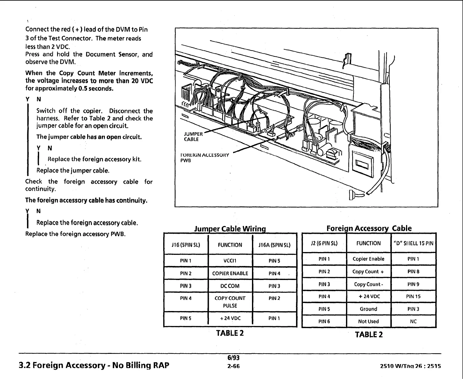
Connect the red
(
+
)
lead of the DVM to Pin
3
of the Test Connector. The meter reads
less than
2
VDC.
Press and hold the Document Sensor, and
observe the DVM.
When the Copy Count Meter increments,
the voltage increases to more than
20
VDC
for approximately
0.5
seconds.
Switch off the copier. Disconnect the
harness. Refer to Table
2
and check
the
jumper cable for an open circuit.
The jumper cable has
en
open circuit.
Y
N
I
lleplvce the foreign accessory kit.
Replace the jumper cable.
Check the foreign accessory cable for
continuity.
The foreign accessory cable has continuity.
I
Replace the foreign accessory cable.
Replace the foreign accessory
PWB.
I
OIkIUN
ACCLSSOKY
PWB
Jumper Cable Wiring
r
)I
I
(WIN
IL)
I
FUNCTION
I
I1
6A
(SPIN
9.)
I
PIN
1
VCCll PIN
5
I
Foreign Accessory Cable
I
PIN
1
Copier
Enable
PIN 1
PIN
2
Copy
Count
+
PIN
8
Copy
Count
-
+
24
VDC
PIN
15
Ground
PIN
3
I
PIN6
1
Not
Used
1
NC
I
TABLE
2
TABLE
2
3.2
Foreign Accessory
-
No
Billing
RAP
 Loading...