C
-
Cover lnterlock Open
RAP
(2510
WI
TAG
5;
251
5)
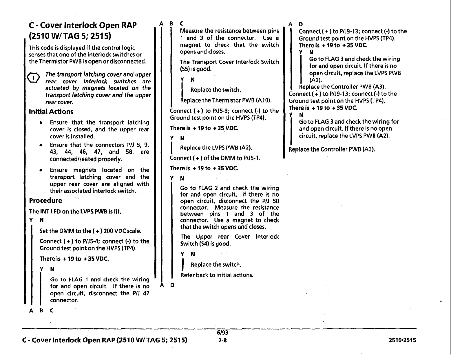
This code
is
displayed if the control logic
senses that one of the interlock switches or
the Thermistor
PWB
is
open or disconnected.
The transport latching cover and upper
rear cover interlock switches are
actuated
by
magnets located on the
transport latching cover and the upper
rear cover.
Initial Actions
Ensure that the transport latching
cover
is
closed, and the upper rear
cover is installed.
Ensure that the connectors
PIJ
5,
9,
43, 44, 46, 47,
and
58,
are
connectedlseated properly.
Ensure magnets located on the
transport latching cover and the
upper rear cover are aligned with
their associated interlock switch.
Procedure
The INT
LED
on the
LVPS PWB
Is
lit.
Y
N
Set the
DMM
to the
(
+
)
200
VDC
scale.
Connect
(
+)
to
PIJ5-4;
connect
(-)
to the
Ground test point on the
HVPS (TP4).
There
is
+
19
to
+
35
VDC.
Y
N
Go to
FLAG
1
and check the wiring
for and open circuit. If there
is
no
open circuit, disconnect the
PIJ
47
connector.
ABC
C
Measure the resistance between pins
1
and
3
of the connector. Use a
magnet to check that the switch
opens and closes.
The Transport Cover lnterlock Switch
($5)
is
good.
Y
N
I
Replace the switch.
Replace the Thermistor
PWB
(A10).
mnect
(+
1
to
PlJ5-3:
connect
(-1
to the
Cc
Ground testFpoint on the
HVPS (TP4).
There
is
+
19
to
+
35
VDC.
I
Replace the
LVPS PWB (A2).
Connect
(
+
)
of the
DMM
to
PIJ5-1.
There
is
+
19
to
+
35
VDC.
Go to
FLAG
2
and check the wiring
for and open circuit. If there
is
no
open circuit, disconnect the
PIJ
58
connector. Measure the resistance
between pins
1
and
3
of the
connector. Use a magnet to check
that the switch opens and closes.
The Upper rear Cover lnterlock
Switch
($4)
is
good.
I
Replace the switch.
Refer back to initial actions.
Connect
(
+
)
to
PIJ9-13;
connect
(-)
to the
Ground test point on the
HVPS (TP4).
There
is
+
19
to
+
35
VDC.
Y
N
Go to FLAG
3
and check the wiring
for and open circuit. If there
is
no
open circuit, replace the
LVPS PWB
(A2).
Replace the Controller
PWB (A3).
Connect
(
+
)
to
PlJ9-13;
connect
(-)
to the
Ground test point on the
HVPS (TP4).
There
is
+
19
to
+
35
VDC.
Y
N
Go to FLAG
3
and check the wiring for
and open circuit. If there
is
no open
circuit, replace the
LVPS
PWB
(A2).
Replace the Controller
PWB (A3).
6/93
C
-
Cover
Interlock
Open
RAP
(2510 WI
TAG
5;
251
5)
2-8
25101251 5
 Loading...