MutliLINX
™
Cable
Hardware User Guide 2-3
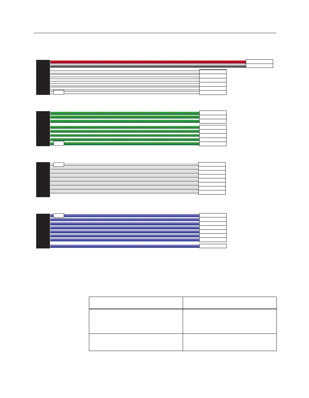
Figure 2-1 MultiLINX Flying Wires
The MultiLINX Flying wires are described in the following table.
Table 2-2 MultiLINX Pin Descriptions
Signal Name Function
PWR Power — Supplies VCC to cable
(Works at multiple voltages 5V,
3.3V, and 2.5V).
GND Ground — Supplies ground refer-
ence to cable.
PWR
GND
CCLK
DONE(D/P)
DIN
PROG
INIT
RST
RT
RD(TDO)
TRIG
TDI
TCK
TMS
CLK1-IN
CLK1-OUT
CS0(CS)
CS1
CS2
CLK2-IN
CLK2-OUT
WS
RS(RDWR)
RDY/BUSY
D0
D1
D2
D3
D4
D5
D6
D7
MultiLINX Flying Lead Connector Set #1
TM
MultiLINX Flying Lead Connector Set #2
TM
MultiLINX Flying Lead Connector Set #3
TM
MultiLINX Flying Lead Connector Set #4
TM
1
2
3
4
X8919