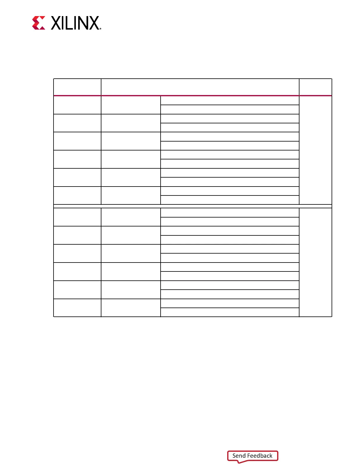
The following table lists the zSFP+ module control and status connecons.
Table 19: zSFP0- zSFP1 Module Control and Status Connections
zSFP Control/
Status Signal
Board Connection
zSFP
Module
SFP0_TX_FAULT Test point J276
High = Fault
zSFP0 J287
lower
Low = Normal operation
SFP0_TX_DISABLE Jumper J35
Off = SFP disabled
On = SFP enabled
SFP0_MOD_DETECT Test point J31
High = Module not present
Low = Module present
SFP0_RS0
1
PU R1420/PD R1426
PU R25 = Full RX bandwidth
PD R30 = Reduced RX bandwidth
SFP0_RS1
1
PU R1421/PD R1427
PU R227 = Full RX bandwidth
PD R142 = Reduced RX bandwidth
SFP0_LOS Test point J33
High = Loss of receiver signal
Low = Normal operation
SFP1_TX_FAULT Test point J30
High = Fault
zSFP1 J287
upper
Low = Normal operation
SFP1_TX_DISABLE Jumper J32
Off = SFP disabled
On = SFP enabled
SFP1_MOD_DETECT Test point J277
High = Module not present
Low = Module present
SFP1_RS0
1
PU R1428/PD R1431
PU R182 = Full RX bandwidth
PD R190 = Reduced RX bandwidth
SFP1_RS1
1
PU R1429/PD R1432
PU R185 = Full RX bandwidth
PD R202 = Reduced RX bandwidth
SFP1_LOS Test point J278
High = Loss of receiver signal
Low = Normal operation
Notes:
1. The RS0/RS1 PU/PD resistors are not populated. There are pull-down resistors built into the SFP/zSFP modules that
select the lower bandwidth mode of the module.
For addional informaon about the enhanced SFP+ module, see the SFF-8431 specicaon at
the SNIA website.
The zSFP connector I2C interfaces are connected to the I2C bus via the TCA9548 I2C
mulplexer U214 (see PMC MIO[46:47] I2C0 Bus and PMC MIO[44:45] I2C1 Bus for more
details).
The detailed ACAP connecons for the feature described in this secon are documented in the
VCK190 board XDC le, referenced in Appendix B: Xilinx Design Constraints.
Chapter 3: Board Component Descriptions
UG1366 (v1.0) January 7, 2021 www.xilinx.com
VCK190 Board User Guide 54

 Loading...


