Appendix C
Pmod FMC
The Pmod FMC-XM119 board is for accessing Pmod standard devices or general purpose I/O
from the base development board. The Pmod standard uses 100 mil space, 25 mil square, and pin
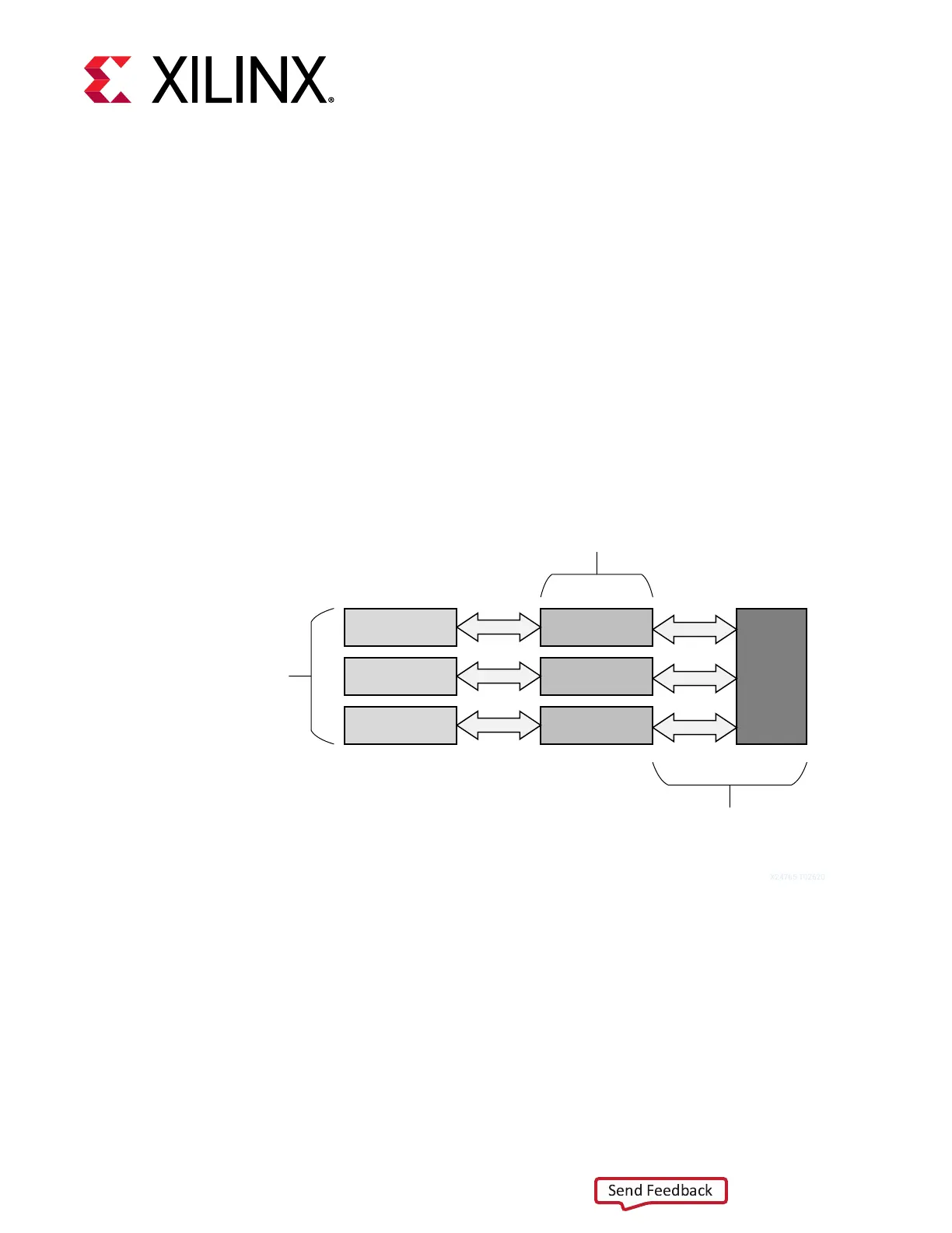
header style connectors. The following gure shows a basic block diagram of the main
components on the Pmod FMC. The basic funcon of this board is to provide a Pmod compable
standard connected to the PL I/O of the Versal™ ACAP. For more informaon, see the Digilent
Pmod Interface Specicaon.
Figure 28: Pmod FMC Block Diagram
Pmod1
Pmod2
Pmod3
Level Shifter
Level Shifter
Level Shifter
Pmod
Connectors
3.3 V Level
Shifters
FMC+
1.5V I/O
(Versal ACAP)
X24765-102620
X24765-102620
The FMC-XM119 board provides three Pmod 12 pin connectors. There are voltage level
translators on the I/O side from the ACAP because of voltage compability with the bank xed
voltages. See the Versal ACAP SelectIO Resources Architecture Manual (AM010) for details on bank
voltages.
Appendix C: Pmod FMC
UG1366 (v1.0) January 7, 2021 www.xilinx.com
VCK190 Board User Guide 71

 Loading...


