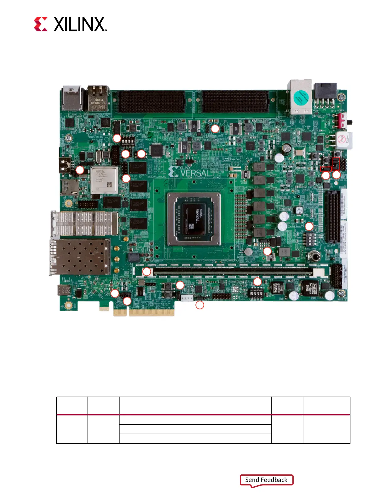
Figure 4: Board Jumper Header and Switch Locations
7
5
8
9
3
14
6
16
11
4
12
2
13
15
1
10
X23150-121420
Jumpers
The following table lists the default jumper sengs.
Table 3: Default Jumper Settings
Callout
Number
Ref. Des. Function Default
Schematic
Page
1 J12
SYSMON VREFP
1-2 12
1-2: 1.024V VREFP connected to ACAP
2-3: VREFP connected to GND
Chapter 2: Board Setup and Configuration
UG1366 (v1.0) January 7, 2021 www.xilinx.com
VCK190 Board User Guide 18

 Loading...


