60 www.xilinx.com Embedded Tri-Mode Ethernet MAC User Guide
UG074 (v2.2) February 22, 2010
Chapter 3: Client, Host, and MDIO Interfaces
R
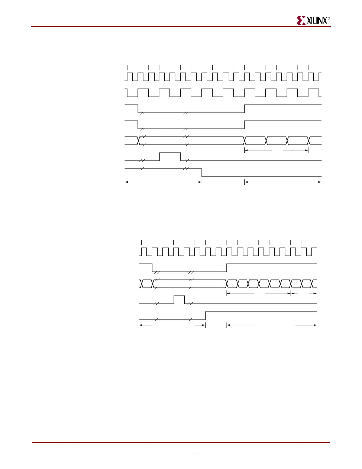
Figure 3-25 shows the timing diagram when a frame matches a valid location in the AF
(16-bit mode). The address filter is disabled in this timing diagram.
Figure 3-26 shows the timing diagram when a frame fails to match a valid location in the
AF (8-bit mode) and the frame drop signal is generated. The address filter is disabled in
this timing diagram.
Figure 3-25: Frame Matching Timing Diagram (16-Bit Mode)
nn–4n–5 n–2 n–1n–3 n+1 n+2 n+3 n+4 n+5 n+6
CLIENTEMAC#RXCLIENTCLKIN
EMAC#CLIENTRXDVLD
EMAC#CLIENTRXD[15:0]
EMAC#CLIENTRXGOODFRAME
PHYEMAC#RXCLK
EMAC#CLIENTRXFRAMEDROP
Previous Frame
Dropped
Current Frame
Passed
DA
DA1, DA0 DA3, DA2 DA5, DA4
ug074_3_27_080805
EMAC#CLIENTRXDVLDMSW
Figure 3-26: Frame Matching Failed Timing Diagram (8-Bit Mode)
nn–1n–2 n+1 n+2 n+3 n+4 n+5 n+6 n+7
CLIENTEMAC#RXCLIENTCLKIN
EMAC#CLIENTRXDVLD
EMAC#CLIENTRXD[7:0]
EMAC#CLIENTRXGOODFRAME
EMAC#CLIENTRXFRAMEDROP
Previous Frame
Passed
Current Frame
Dropped
DA SA
u
074_3_28_080805