Operator Cab
iiWAR
A
A brief description
of
controls, indica-
tors, and instruments is provided as a
convenience
for
the operator. These
descriptions
DO
NOT provide com-
plete operation
instructions.
Read
and understand
the
entire manual
to
prevent
equipment damage, injury,
or
death.
Ignition Switch
---
A
key
is
required
to
actuate the ignition switch.
Figure 6-1. Key And Ignition Switch.
The ignition switch
has
four
(4)
positions:
OFF,
RUN,
PREHEAT,
and
START.
Table
5.
Ignition
Switch
Position
Purpose
OFF
Shuts down entire electrical system, except
the
horn
and
accessory oul[et.
RUN
AI[
controls and indicators
are
operable.
PREHEAT
Use
for cold slarting conditions.
START
Engages starter motor
to
crank engine.
NOTE: The PREHEAT
and
START positions are
spring-loaded, When the
key
is released, the igni-
tion switch will automatically return
to
the
RUN
posi-
tion,
Xtreme Manufacturing
28
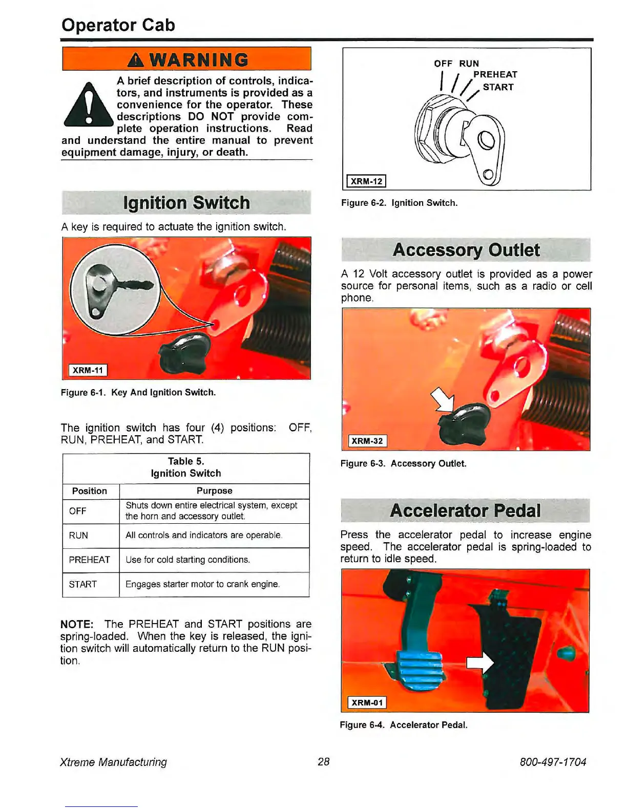
OFF RUN
I
/
PREHEAT
I/START
IXRM-12I
Figure 6-2. Ignition Switch.
Accessory Outlet
A
12
Volt accessory outlet
is
provided
as
a power
source for personal items, such
as
a radio or cell
phone.
IXRM-32I
Figure 6-3. Accessory Outlet.
Aocelerator Pedal
.....
_
......
,,;;.;.,
.....
Press the accelerator pedal
to
increase engine
speed, The accelerator pedal
is
spring-loaded to
return
to
idle speed,
Figure 6-4. Accelerator Pedal.
800-497-1704