Using Load Capacity Charts
The reach forklift includes two
(2)
indicators
to
assist
the operator for accurately using the load capacity
charts. These indicators are the Boom Extend
Letters and the Boom Angle Indicator.
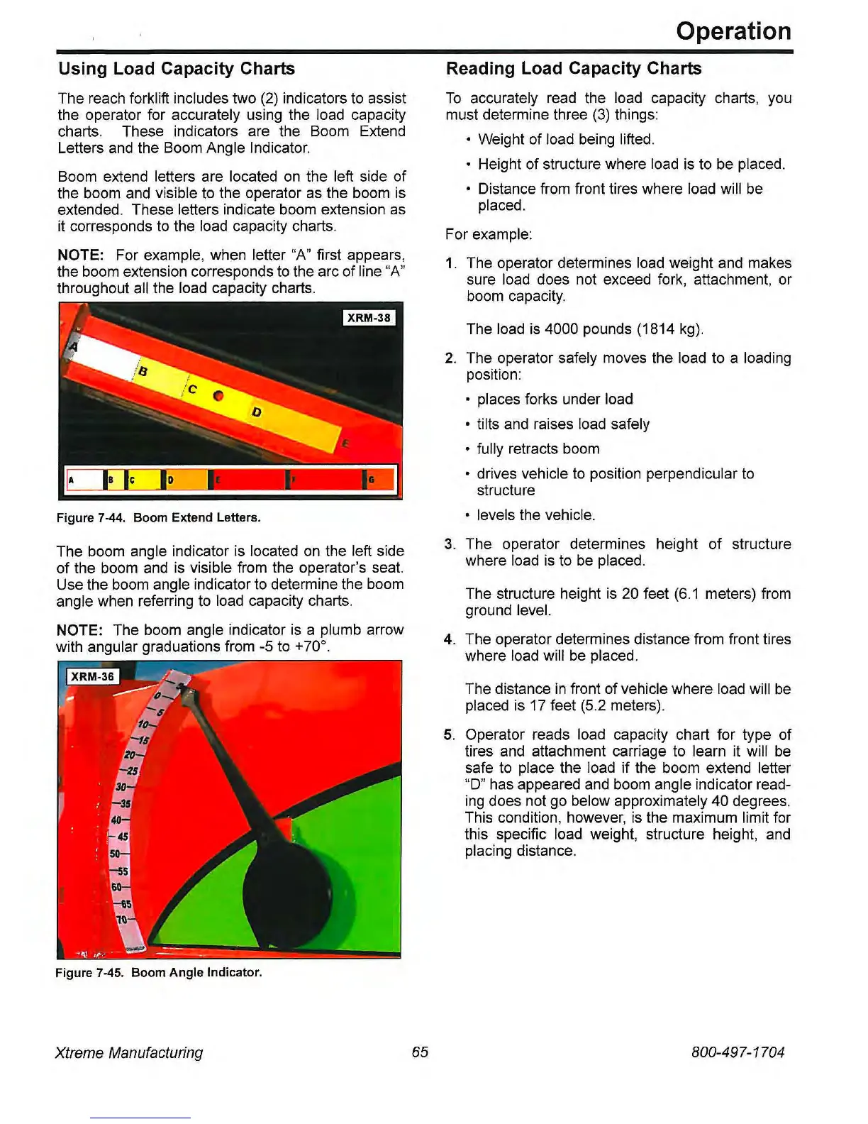
Boom extend letters are located
on
the left side of
the boom and visible to the operator
as
the boom is
extended. These letters indicate boom extension
as
it corresponds
to
the load capacity charts.
NOTE: For example, when letter
"A"
first appears,
the boom extension corresponds
to
the arc of line
"A"
throughout all the load capacity charts.
Figure
7-44.
Boom Extend Letters.
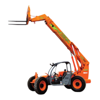
The boom angle indicator is located
on
the left side
of the boom
and
is
visible from the operator's seat.
Use the boom angle indicator
to
determine the boom
angle when referring
to
load capacity charts.
NOTE: The boom angle indicator
is
a plumb arrow
with angular graduations from -5
to
+70
0
•
Figure
7-45.
Boom Angle Indicator.
Xtreme Manufacturing
65
Operation
Reading Load Capacity Charts
To
accurately read the load capacity charts, you
must determine three
(3)
things:
o Weight of load being lifted.
o Height of structure where load is
to
be placed.
o Distance from front tires where load will
be
placed.
For example:
1.
The operator determines load weight and makes
sure load does not exceed fork, attachment, or
boom capacity.
The load
is
4000 pounds (1814
kg).
2.
The operator safely moves the load to a loading
position:
• places forks under load
o tilts and raises load safely
o fully retracts boom
• drives vehicle
to
position perpendicular
to
structure
• levels the vehicle.
3.
The operator determines height of structure
where load is to
be
placed.
The structure height is 20 feet
(6.1
meters) from
ground level.
4.
The operator determines distance from front tires
where load will
be
placed.
The distance
in
front of vehicle where load will
be
placed is 17 feet (5.2 meters).
5.
Operator reads load capacity chart for type of
tires and attachment carriage
to
learn it will
be
safe
to
place the load
if
the boom extend letter
"D" has appeared and boom angle indicator read-
ing
does not go below approximately 40 degrees.
This condition, however,
is
the maximum limit for
this specific load weight, structure height,
and
placing distance.
800-497-1704