EasyManuals Logo

Yamatake MGG14C User Manual

Default Icon
134 pages
To Next Page IconTo Next Page
To Previous Page IconTo Previous Page
Page #39 background imageLoading...
Page #39 background image
2 - 14
Electrical Wiring (6)
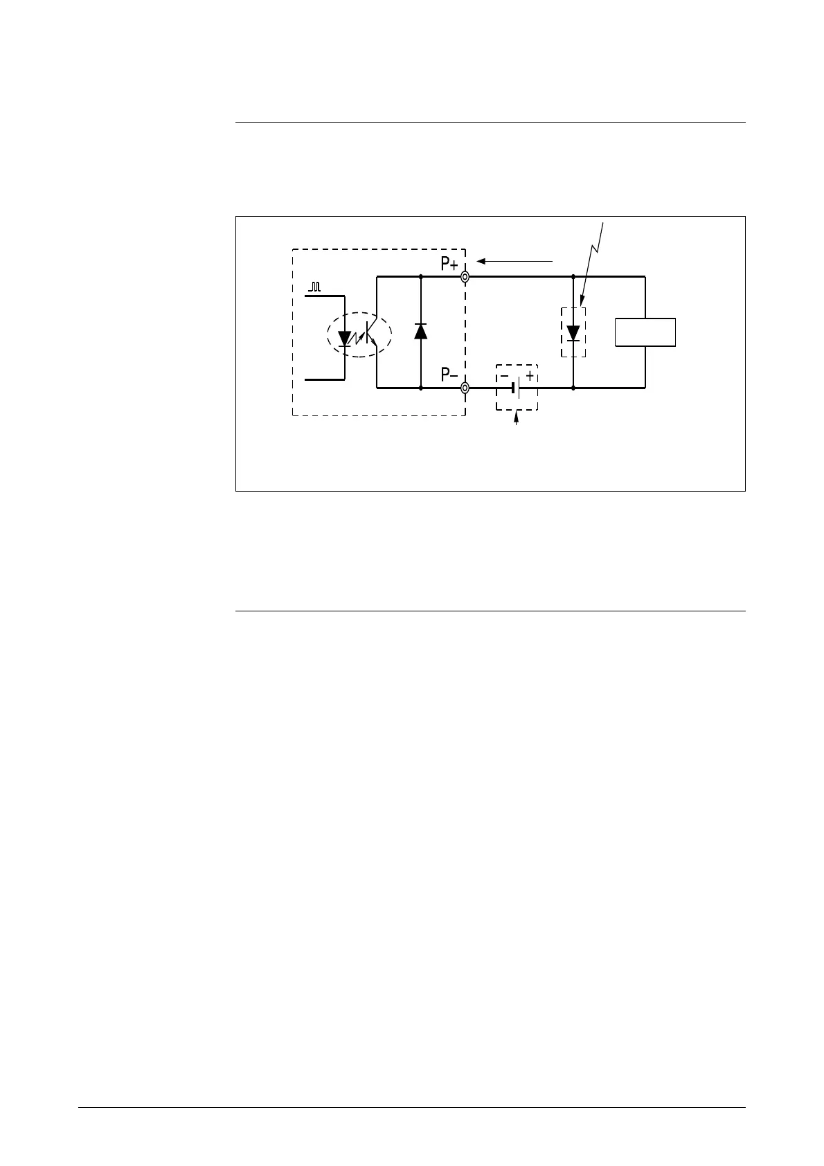
Pulse output wiring
The pulse output is an open collector output.
Pay close attention to voltage and polarity when wiring.
Figure 2-12 Wiring diagram for pulse output
Protective diode
200mA max.
Load
this is impossible
Note:
Miswiring of polarity may cause damage to the equipment.
Recheck the wiring position carefully.
Use an external power supply with voltage and capacity that satisfy
the specifications.
External
power supply
30V max.

Table of Contents

Questions and Answers:

Question and Answer IconNeed help?

Do you have a question about the Yamatake MGG14C and is the answer not in the manual?

Yamatake MGG14C Specifications

General IconGeneral
BrandYamatake
ModelMGG14C
CategoryMeasuring Instruments
LanguageEnglish

Related product manuals