4 - 34
Range Functions Continued
Automatically switches the range when the fluid flow direction reverses.
Hysteresis is available at the time of normal/reverse switching.
Analog output
Normal direction: 4 - 20 mA DC
Reverse direction: 4 - 20 mA DC
When there is a pulse output
There is no distinction in output between the normal and reverse direc-
tions. The pulse scale is also the same.
The built-in counter simply integrates the flow rate without distinguish-
ing normal and reverse directions. However, when normal/reverse dif-
ferential flow integration is selected, integration of the "-" direction (sub-
traction) is available.
Example: In the normal direction
-100 → -99 → -98 ··· 0 → 1, 2, 3
In the reverse direction
100 → 99 → 98 ··· 0 → 1, 2, 3
With indication
With a reverse flow rate, the "-" symbol will appear on the flow rate dis-
play. With a pulse output, it is possible to select the normal/reverse dif-
ferential flow integration function.
Contact output
Normal/reverse distinction status signal
The contact output status at shipment is as follows.
Range No.1: Open
Range No.2: Closed
Reverse setting is also possible.
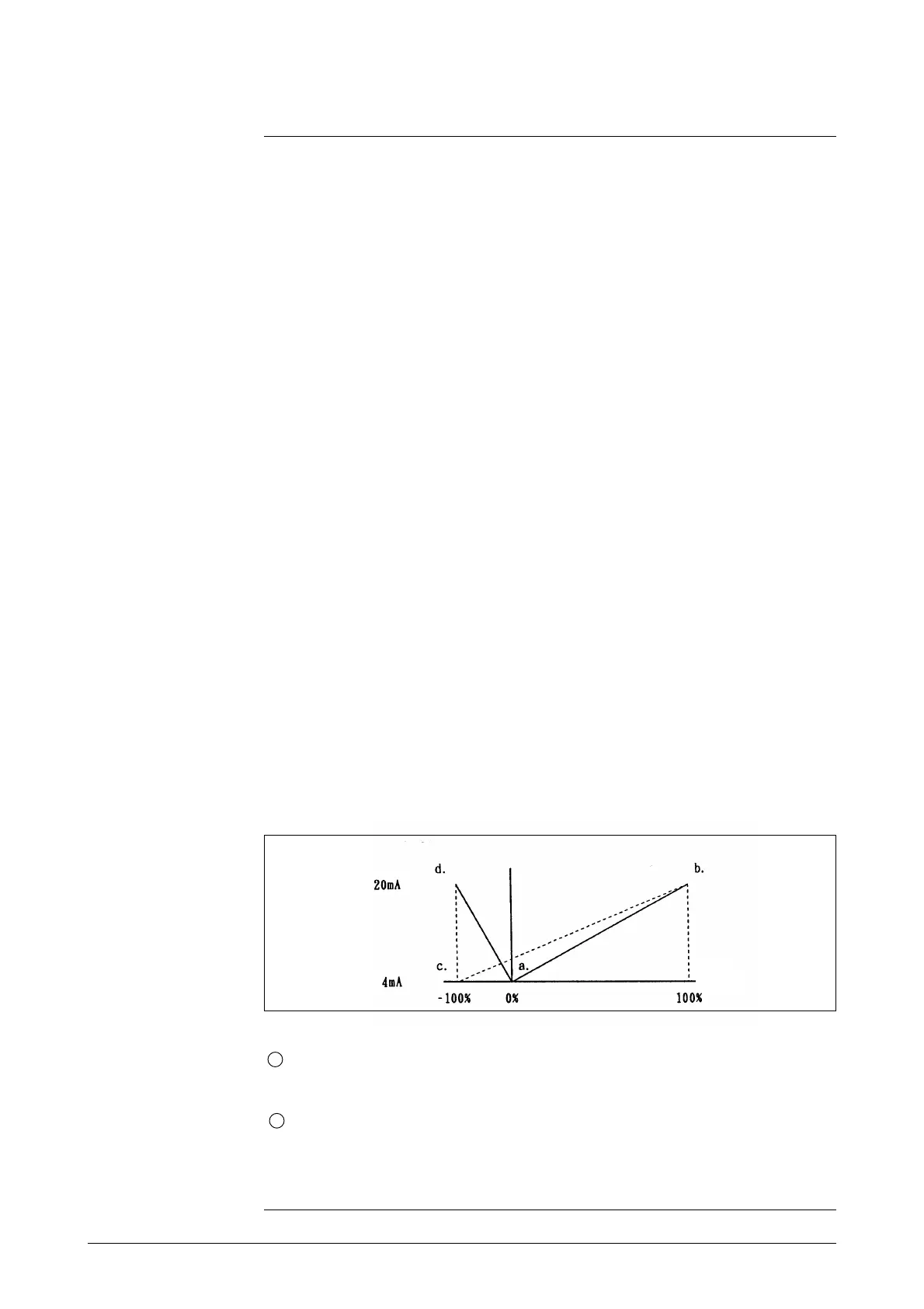
Figure 4-3 Normal/reverse automatic switching range
Normal/reverse
automatic switching
range
(Example of setting)
1 AUTO range
• Range No.1 (narrow range): Outputs 4 - 20 mA for 0 - 10 m
3
/h (a - d).
• Range No.2 (wide range): Outputs 4 - 20 mA for 0 - 43 m
3
/h (a - b).
2 WIDE range
• Range No.1 (narrow range): Outputs 4 - 8 mA for 0 - 10 m
3
/h (a - d).
• Range No.2 (wide range): Outputs 8 - 20 mA for 0 - 30 m
3
/h (c - b).
When WIDE in selected, Low-flow-cut is not performed.
(Continued on next page)
Output
Input