2 - 15
Electrical Wiring (7)
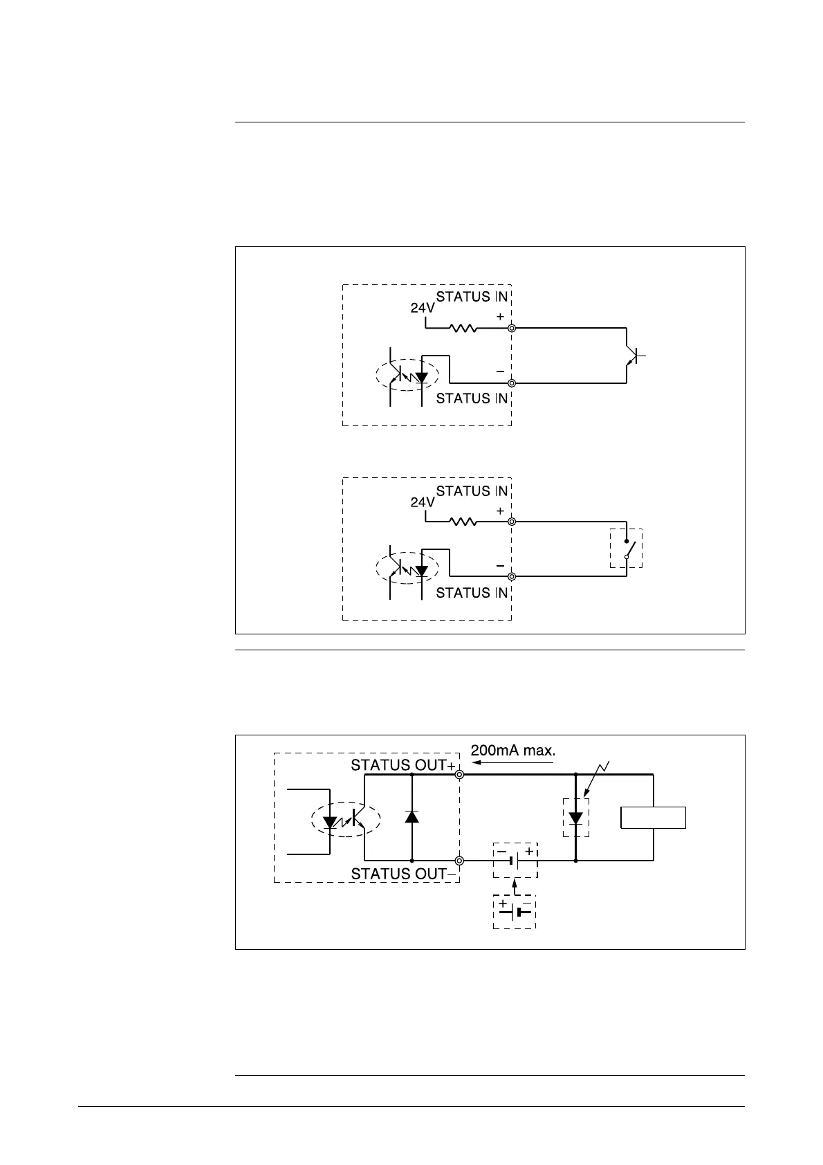
Contact input wiring
Either a semiconductive contact or a no-voltage contact can be used as the
contact input.
The contact input/output terminals are not available when a 2-contact output
model has been selected.
Figure 2-13 Wiring diagram for contact input
Contact output
wiring
Pay close attention to voltage and polarity when wiring, because this is an
open collector output.
Figure 2-14 Wiring diagram for contact output
• Semiconductive contact input
• No-voltage contact input
Protective diode
Load
External power supply 30V max.
this is impossible
Note:
• Miswiring of polarity may cause damage to the equipment.
Recheck wiring position carefully.
Use an external power supply with voltage and capacity that
satisfy the specifications.