ENGINE
Assembling the Engine and Components
5-70 6LY3 Service Manual
© 2007 Yanmar Marine International
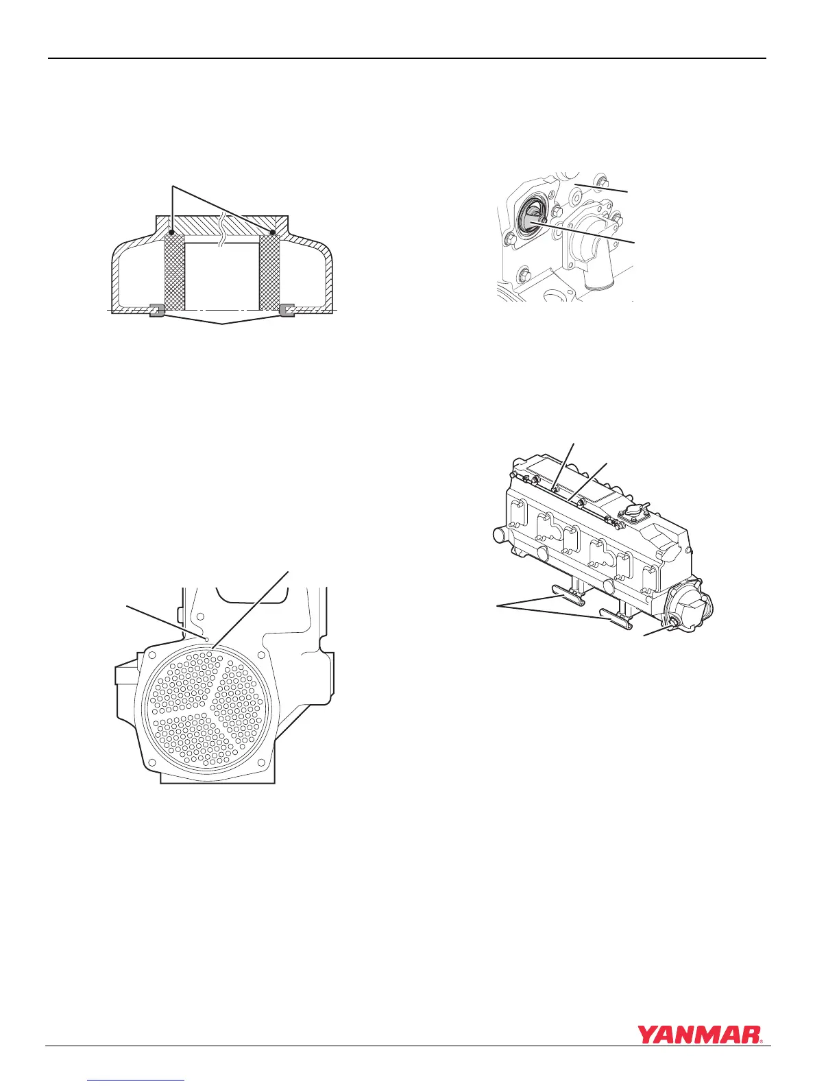
Installing the Heat Exchanger
1. Apply silicone grease to both of the O-rings
(Figure 5-118, (2)) and install on both ends of
the cooler core.
Figure 5-118
Figure 5-118
1 – Coolant Pump End
2–O-Ring
3 – Flywheel End
4 – Separator Seal
2. Insert the core into the cooler body.
3. Align the notch in the core
(Figure 5-119, (2)) with the centering hole
(Figure 5-119, (1)) in the cooler body.
Figure 5-119
Figure 5-119
1 – Notch in Core
2 – Centering Hole
4. Fit the separator seal to both side covers (water
pump end and flywheel end). See
Figure 5-118.
5. Fit the side cover to the heat exchanger.
Installing the Coolant Tank
1. Fit the O-ring on the thermostat
(Figure 5-120, (2)) and insert the thermostat
into the coolant tank (Figure 5-120, (1)).
Figure 5-120
Figure 5-120
2. Secure the coolant tank with bolts.
3. Tighten the bolts to the specified torque value.
4. Install the air line (Figure 5-121, (2)).
Figure 5-121
Figure 5-121
1 – Coolant Plug
2 – Air Line
3 – Zinc Anode
4 – Brackets
5. Install the zinc anode
(Figure 5-121, (3)).
6. Install the brackets to the cylinder block
(Figure 5-121, (4)).
0005820
(2)
(4)
(1) (3)
0005822
(2)
(1)
0005823
(1)
(2)
0005824
(1)
(2)
(3)
(4)

 Loading...


