ENGINE
Inspecting the Cylinder Block and Components
5-48 6LY3 Service Manual
© 2007 Yanmar Marine International
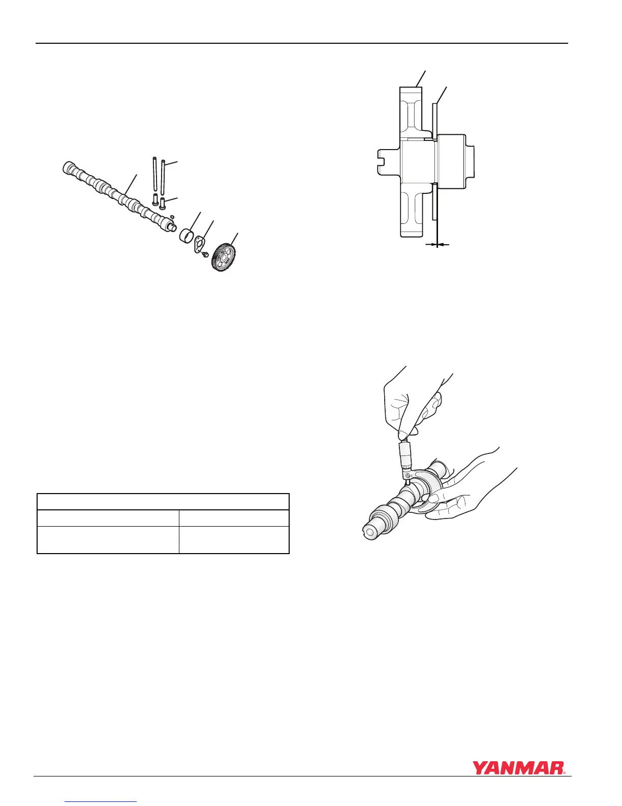
Inspecting the Camshaft and Tappets
The camshaft (Figure 5-64, (1)) is normalized. The
cam lobes and bearing surfaces are surface
hardened and ground with a curve that minimizes
the repeated shocks on the valve seats and
maximizes valve seat life.
Figure 5-64
Figure 5-64
1–Camshaft
2–Push Rod
3–Tappet
4 – Camshaft Bearing
5 – Thrust Bearing
6–Camshaft Gear
Inspecting the Camshaft Side Clearance
NOTICE: Measure the thrust clearance before
disassembling.
The cam gear (Figure 5-65, (1)) and camshaft are
assembled using a shrink-fit. Use caution when
replacing the cam thrust bearing.
Figure 5-65
Figure 5-65
1–Cam Gear
2 – Thrust Metal
3 – Side Clearance
• Measure the height of each cam lobe as shown in
Figure 5-66.
Figure 5-66
Figure 5-66
• Replace the cam if any lobes are worn beyond
the stated limit.
Camshaft Side Clearance
Standard Limit
0.05-0.20 mm
(0.0019-0.0078 in.)
0.29 mm
(0.0114 in.)
0005649
(1)
(2)
(3)
(4)
(6)
(5)
0005650
(1)
(2)
(3)
0005651

 Loading...


